This article is approximately 5,700 words long, recommended for saving and reading.
Author | Zuo Chenggang
Produced by | Automotive Electronics and Software
Introduction:
This article is the eleventh piece in the series of articles titled《Automotive Grade Testing of ECUs》 (click to view all articles).Continuing from the previous text, this article will continue to introduce theGB/T 21437 standard, butGB/T 21437 is a complex standard that includes both conducted emissions and immunity content.
To facilitate understanding, according to the philosophy of our series of articles, the introduction of the standard is divided according to the dimension of interference/emission (disturbance) and immunity, and then explained step by step. All standards and tests related to interference/emission have been fully discussed previously, and what we will discuss next will be entirely about the immunity section.This article is aboutGB/T 21437.2 standard regarding transient immunity along power lines andGB/T 21437.3 transient immunity of non-power lines, both of which fall under the category of conducted immunity.
All test items in this article are accompanied by real DV test photos, including test equipment, samples, test setups, test limits, and result determinations, helping everyone gain a deeper understanding and recognition of DV testing. Special thanks to CVC Weikai Testing Technology for providing laboratory technical support and test photos..
*Note: Some content of this article is excerpted from the author’s new book《Reliability Design and Development Practice of General Automotive Grade Electronic Components》, published by the Machinery Industry Press in June 2024, and has been adapted during the excerpt. This article contains a lot of content, and it is recommended to save and read.The table of contents is as follows:
1. Transient immunity along power lines
1.1 Immunity test pulses
1.2 Severity levels of test pulses
1.3 Value and limitations of standard tests
2. DV testing of transient immunity along power lines
2.1 DV test levels and requirements
2.2 Arrangement of DV tests
2.3 Result determination
3. Transient immunity coupled to non-power lines
3.1 General provisions
3.2 Test pulses
3.3 Test arrangement
3.4 Capacitive coupling clamp (CCC) method
3.5 Direct capacitive coupling (DCC) method
3.6 Inductive coupling clamp (ICC) method
3.7 Test summary
4. DV testing of transient immunity coupled to non-power lines
4.1 DV test levels and requirements
4.2 Arrangement of CCC method DV tests
4.3 Arrangement of ICC method DV tests
4.4 Result determination
GB/T 21437.2, the first part of the standard discusses transient conducted emissions, while the latter part discusses immunity, andGB/T 21437.3 discusses immunity entirely, which can easily confuse those encountering this standard for the first time. To facilitate distinction and understanding, the following diagram is provided again:
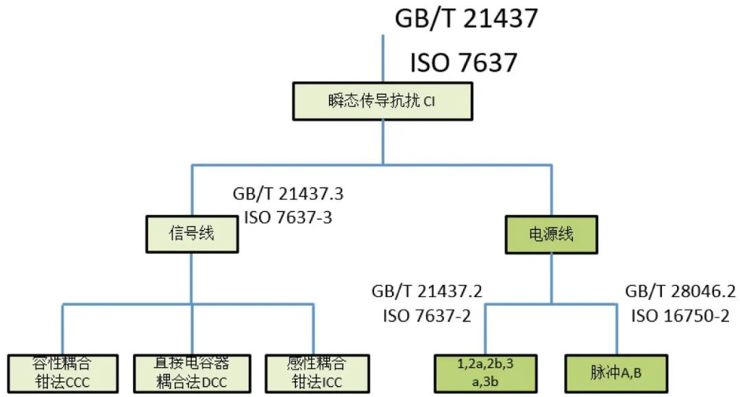
EMC Conducted immunity related standards (Source: Zuo Chenggang “General Automotive Grade”)
#01
Transient immunity along power lines
The standard that specifies the transient conducted immunity along power lines is part 2 of GB/T 21437 (GB/T 21437.2 Part 2: Transient Conducted Emissions and Immunity along Power Lines).
1) General provisions
The DUT should be placed on a non-conductive support 50mm above the grounding plate, with the grounding method of the shell conforming to the actual connection of the vehicle. For test pulses3a and3b, the length of the power line between the pulse generator and the DUT port should be 500mm ± 100mm, placed straight and parallel on a non-conductive support 50mm ± 5mm. The load simulator should preferably be placed directly on the grounding plate. If the load simulator has a metal shell, its shell should be connected to the grounding plate.
2) Test arrangement
The test arrangement is shown in the following diagram:
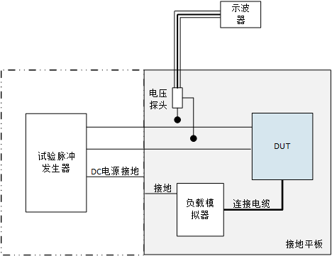
Transient immunity test arrangement (Compiled by: Zuo Chenggang)
1.1 Immunity test pulses
GB/T 21437.2-2021 adopts ISO 7637-2:2011. It should be noted that ISO 7637-2:2011 has deleted pulses4 and load dump5a and5b, pulse4 has been moved to ISO 21848:2005 (the corresponding national standard is GB/T 28045-2011, electrical and electronic equipment for road vehicles with a supply voltage of 42V), which will not be discussed here. The test specifications for load dump pulses have been placed in ISO 16750-2:2012 (the national standard is GB/T 21437.2-2021),5a has become test pulseA(Pulse A)- without centralized load dump suppression,5b has become test pulseB(Pulse B)- with centralized load dump suppression.
Taking a 12V system as an example, the corresponding pulses and parameters for conducted interference are shown in the following table:
|
Pulse |
Peak Voltage |
Pulse Width |
Interference Source Impedance |
|
1 |
-75~-150 |
2ms |
10Ω |
|
2a |
+37 ~ +112 |
50µs |
2Ω |
|
2b |
10 |
0.2s ~ 2s |
0Ω ~ 50mΩ |
|
3a |
-112 ~ –220 |
150ns±45ns |
50Ω |
|
3b |
+75 ~ +15 |
150ns±45ns |
50Ω |
|
A |
+79 ~ +101 |
40ms ~ 400ms |
0.5Ω ~ 4Ω |
|
B |
|
40ms ~ 400ms |
0.5Ω ~ 4Ω |


Conducted interference pulses1~3 are shown in the following diagram:
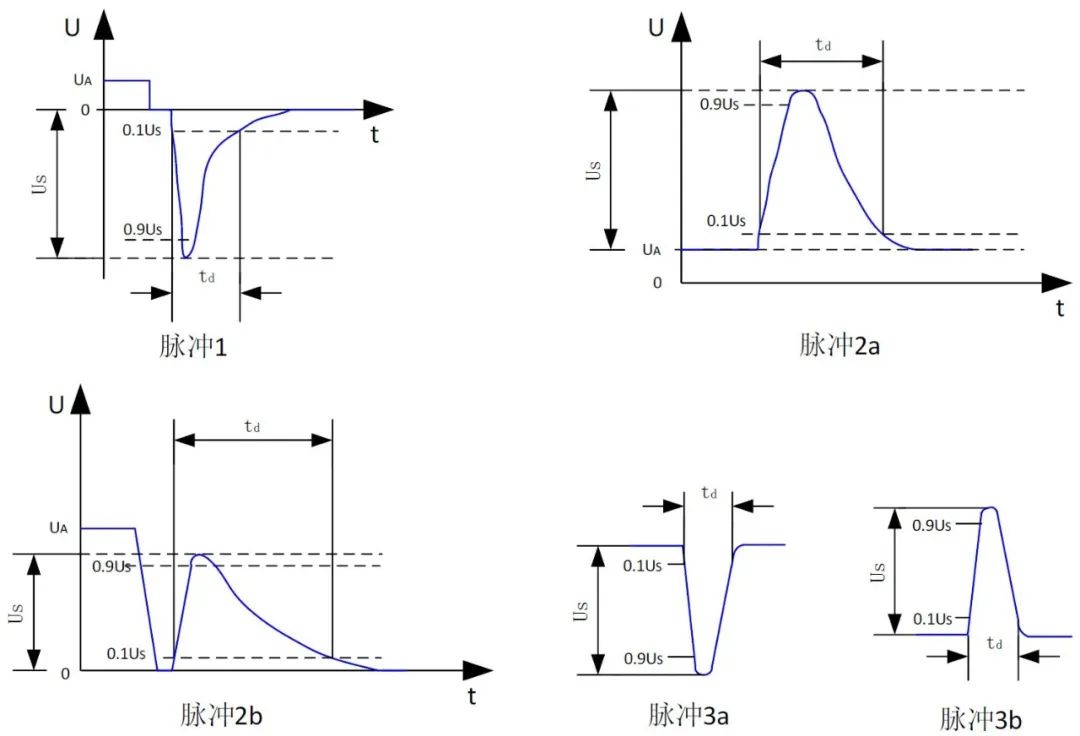
Conducted interference corresponding pulse waveform (Source: Zuo Chenggang “General Automotive Grade”)
PulsesA and pulsesB waveforms are shown in the following diagram:
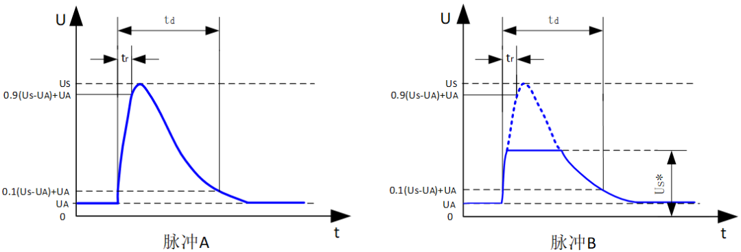
Load dump waveform pulsesA and pulsesB (Source: Zuo Chenggang “General Automotive Grade”)
1.2 Severity levels of test pulses
The minimum and maximum severity levels recommended by the standard are shown in the table with levelsⅢ and levelsⅠ. According to the agreement between vehicle manufacturers and component suppliers, levels and test times can be selected between the values given in the table. In the absence of defined specified values, it is recommended to use the level values corresponding to levelsⅢ and levelsⅣ.
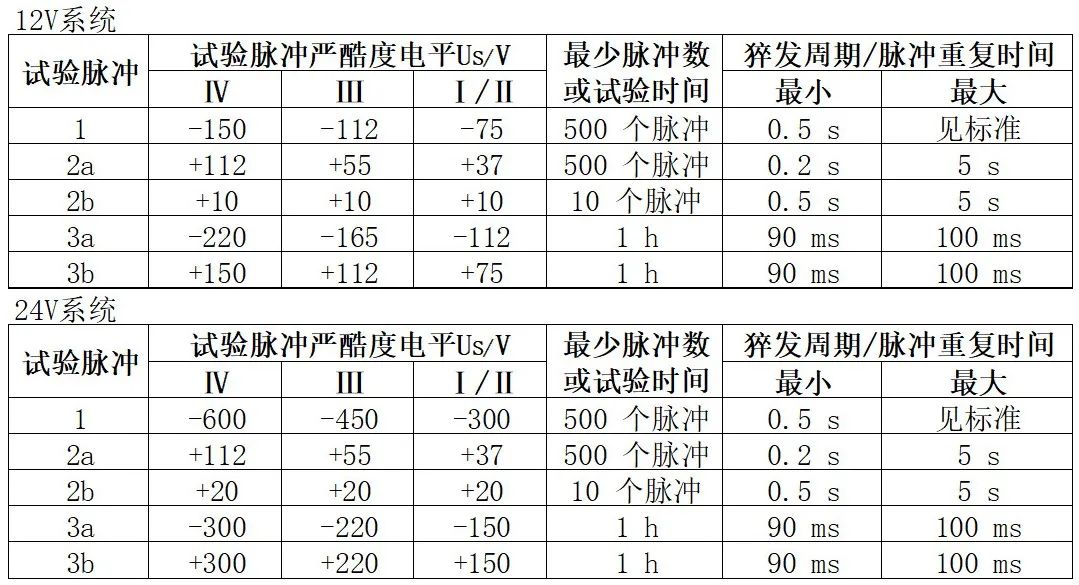
GB/T 21437.2-2021 specifies the severity levels of test pulses (Compiled by: Zuo Chenggang)
1.3 Value and limitations of standard tests
The standard appendix specifically points out the background of the tests and the limitations of the test waveforms, while also providing alternative test methods for simulating complex waveforms in the appendix. Even if there are slight differences between the waveforms in the appendix and the actual waveforms, the determination results do not constitute an impact. Voltage transients are often generated during the switching of inductive loads. The arc phenomenon produces complex voltage waveforms, whose characteristics(such as voltage, pulse duration) are significantly affected by the reactive and resistive loads in the same circuit as the inductive load.
Choosing the test pulses described in the standard(for example, the characteristics of pulse1) reflect the transient waveforms on the power supply circuit of the DUT with an impedance of less than100Ω, mainly related to the input filter capacitance of the circuit. Many microprocessor-based electronic devices have high impedance power and input circuits, and when these high impedance connections are switched on inductive loads, significantly different voltage transient characteristics can occur. Additionally, the actual voltage transient characteristics are inherently non-repetitive, with significant differences between consecutive transient phenomena. This pseudo-random behavior often leads toDUT software execution failures..
To simulate these complex waveforms, the standard appendix provides alternative test methods, namely transient test techniques based on switching inductive loads. The waveforms described in the appendix are typical transients generated by the transient generator circuit defined in the appendix. These waveforms can serve as references for the waveforms produced by the transient generator. Unless otherwise specified, all waveforms should be measured under open-circuit conditions.
Components selected for the transient generator may lead to slight differences between the waveforms in the appendix and the actual waveforms(for example, waveform amplitude, time characteristics). These differences during the test should not significantly alter the determination results of the DUT.
In other words, testing standards have certain limitations, and the standards cannot fully simulate the waveforms of electronic and electrical components like ECUs during actual vehicle applications, but the waveforms selected by the standard have already taken these differences into account, so the test results are acceptable. If the users of the standard believe that the waveforms provided in the standard cannot meet the testing requirements, the standard appendix also provides alternative test methods, which refer to the transient generator circuits given in the appendix to simulate the required pulses for testing.
#02
Transient immunity along power linesDV testing
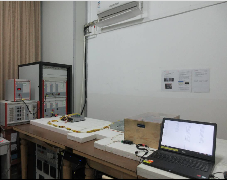
Unlike the previously mentioned interference/emission standards, the tests need to be conducted in a shielded room or anechoic chamber ALSE to eliminate external radio disturbances. The transient immunity testing does not require a dedicated shielded room, only a specialized testing room is sufficient. The test facilities and equipment required for transient immunity testing along power lines are shown in the following diagram (from a real DV report):
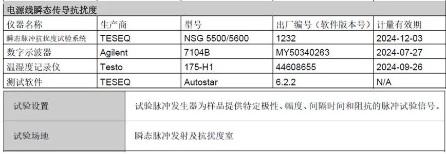
Transient immunity testing equipment for power lines (Source: FQ Technology,CVC Weikai)
The tests are conducted in a transient pulse emission and immunity chamber, and the testing requires the use of transient pulse immunity systems, oscilloscopes, testing software, etc., consistent with the standard requirements.
2.1 DV test levels and requirements
In this DV test, the test levels, requirements, and determination standards for the DUT are as follows:
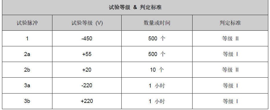
Transient immunity testing requirements for power lines (Source: FQ Technology,CVC Weikai)
As seen in the diagram, the test pulses include pulses1, 2a, 2b, 3a, 3b, which are consistent with the specifications in the standard. Additionally, from the parameters in the diagram, the DUT is a 24V system product.
2.2 Arrangement of DV tests
According to the standard requirements, the test arrangement is shown in the following diagram:
Overall test arrangement (Source: FQ Technology,CVC Weikai)
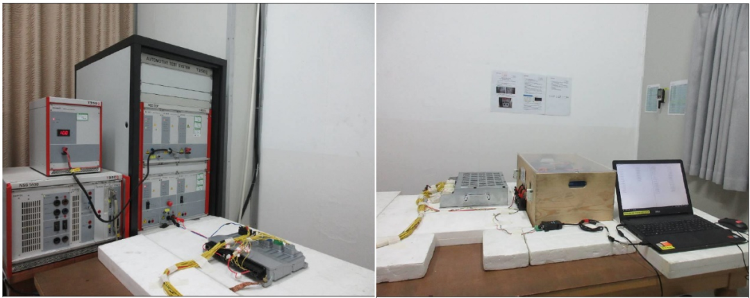
Partial test arrangement (Source: FQ Technology,CVC Weikai)
As seen in the diagram, the test arrangement follows the standard requirements, where the pulse generator applies the test pulses to the DUT power line, and the DUT connects to a simulated load.
2.3 Result determination
The determination of test results is shown in the following diagram:
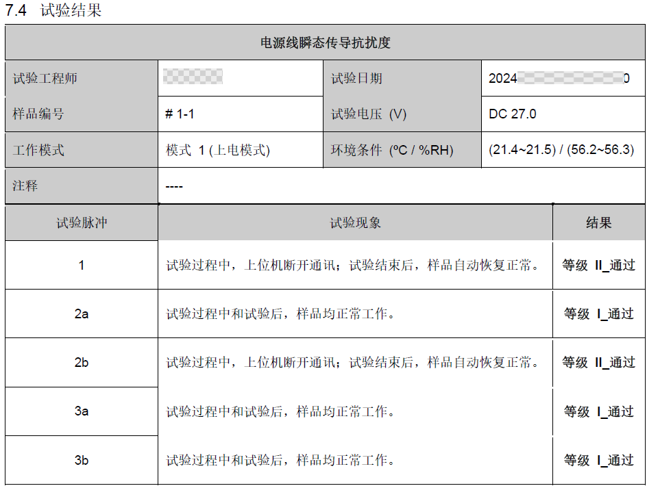
Test results and determination (Source: FQ Technology,CVC Weikai)
As seen in the diagram, the DUT’s operating mode during the test was mode1, with a test voltage of27V (the DUT is a 24V product), and the test results for each pulse met the test requirements.
#03
Transient immunity coupled to non-power lines
The transient immunity of non-power lines is specified in the third part of the standard, which is GB/T 21437.3: Part 3: Immunity to Transients Coupled to Non-Power Lines. The standard describes three test methods for the immunity of electrical/electronic components (DUT) to coupled transient pulses: capacitive coupling clamp (CCC) method, direct capacitive coupling (DCC) method, and inductive coupling clamp (ICC) method.
3.1 General provisions
The test transient pulses simulate fast and slow electrical transient disturbances, such as those caused by inductive load switching, relay contact bouncing, etc. The test pulses provided by the standard are typical pulses that reflect the main characteristics of transient pulses that may occur in vehicles.
Additionally, the standard specifies that if electrical/electronic components are not affected by the pulses specified in this part due to their own functions or structures, these pulses do not need to be applied during the test. Additional test pulses that need to be applied should be defined through negotiation between vehicle manufacturers and component suppliers.
The test plan should at least include the following aspects:
-
Test methods used;
-
Test pulses applied;
-
Pulse amplitude;
-
Number of test pulses;
-
DUT operating mode;
-
Wiring harness (product wiring harness or test wiring harness);
-
Wires used for capacitive coupling clamp method;
-
Wires used for direct capacitive coupling method;
-
Capacitance values used for direct capacitive coupling method;
-
Wires used for inductive coupling clamp method;
-
Type of inductive coupling clamp used for inductive coupling clamp method.
Additionally, test conditions such as temperature, voltage, tolerances, etc., should be in accordance with the provisions of GB/T 21437.1. Power supplies, oscilloscopes and probes, and pulse generators must comply with the provisions of GB/T 21437.1.
The severity levels for the immunity evaluation tests of the DUT are determined through negotiation between vehicle manufacturers and component suppliers and can be selected from the appendix. The table below shows the applicability of the three different test methods. One applicable method can be selected from the slow electrical transient pulse test method and the fast electrical transient pulse test method for the DUT.
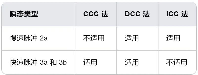
Standard provisions on the applicability of test methods (Compiled by: Zuo Chenggang)
3.2 Test pulses
Test pulses are divided into slow pulses and fast pulses, as follows:
-
Slow pulses include: slow transient pulses2a-positive pulse, slow transient pulse2a-negative pulse, the waveform and parameters of the pulses are specified in the standard.
-
Fast pulses include: fast transient pulses3a, fast transient pulses3b, the waveform and parameters of the pulses are specified in the standard.
The standard specifies the pulse waveforms as shown in the following diagram:
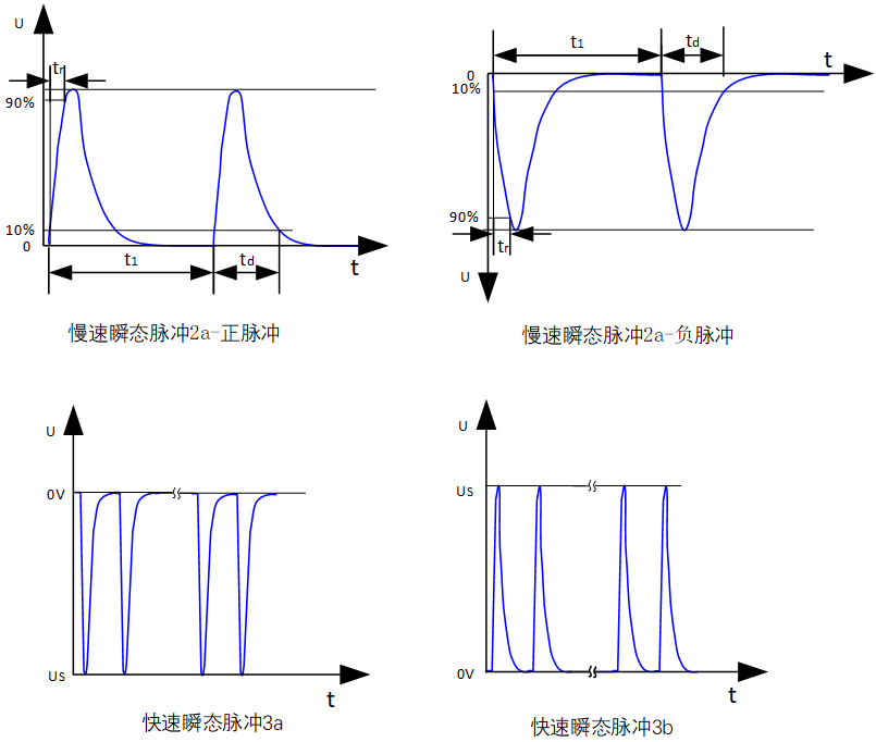
GB/T 21437.3 specifies the transient pulse waveforms (Compiled by: Zuo Chenggang)
3.3 Test arrangement
The DUT should be placed on a non-conductive support 50mm above the grounding plate, and connected to the load simulator. If the actual signal source for the DUT cannot be used, a simulated signal source can be used.
All wiring harnesses should be placed on a non-conductive support 50mm above the grounding plate, and all grounds for loads, sensors, etc. (ground wires, metal shells) should be connected to the grounding plate using the shortest wires possible. To minimize capacitive coupling unrelated to the DUT, the shortest distance between the DUT and all other conductive structures (except for the grounding plate below the test arrangement) such as the walls of the shielded room should be greater than 0.5m.
The specific test arrangement varies according to the test method, and will be introduced separately according to capacitive coupling clamp (CCC) method, direct capacitive coupling (DCC) method, and inductive coupling clamp (ICC) method.
3.4 Capacitive coupling clamp (CCC) method
Capacitive coupling clamp (CCC) couples the test pulses to the tested circuit, with no electrical connection to the DUT, wiring harness, or auxiliary equipment. The materials for CCC can be brass, copper, or galvanized steel.
CCC method is suitable for coupling fast electrical transient test pulses, especially for DUTs with moderate or large numbers of wires. This method is not suitable for coupling slow electrical transient test pulses. The wires passing through the CCC for the DUT are determined through negotiation and recorded in the test plan, with a coupling length of1m. The DUT and the transient pulse generator should be placed at the same end of the CCC. The total length of the tested wiring harness is1700mm~2000mm. In the CCC method, the 12V/24V power lines (positive and return lines) are not included, while other return or positive lines that need to connect to auxiliary equipment (such as sensors) should be included. If the auxiliary equipment is grounded at the near end, the near-end grounding connection should not be included. All excluded return or positive lines should be noted in the test plan. All cables in the CCC should be arranged in a single layer (typically 10 to 20 wires) and placed flat for measuring all DUT cables, allowing for multiple tests.
The arrangement of the DUT should be as shown in the following diagram:
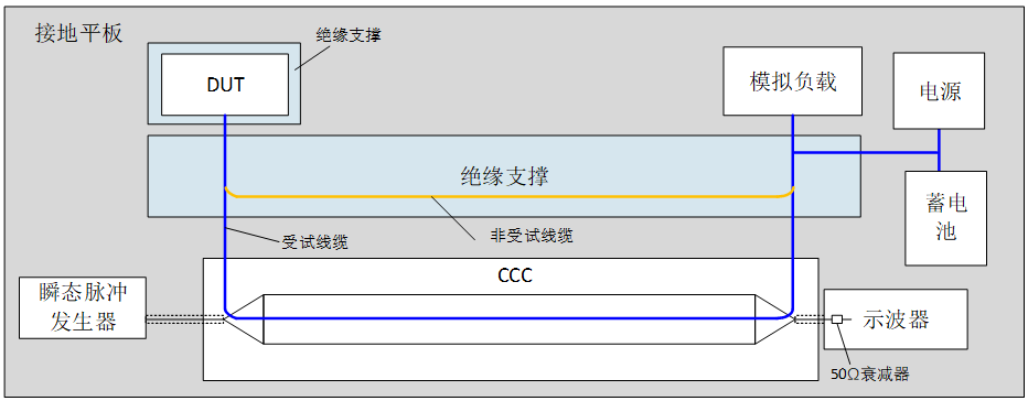
CCC method test arrangement (Compiled by: Zuo Chenggang)
3.5 Direct capacitive coupling (DCC) method
DCC method uses capacitors to achieve electrical transient coupling. The coupling capacitance values are shown in the following table:
|
Test Pulse |
Capacitance Value |
|
Slow electrical transient pulse |
0.1 μF |
|
Fast electrical transient pulse |
100 μF |
DCC method requires the total length of the tested wiring harness to be1700mm~2000mm. For fast transient pulse tests, the generator should be connected to the capacitor via a 50Ω coaxial cable not exceeding 500mm in length. When using the DCC method, each cable of the DUT must be tested individually. However, for twisted pairs and balanced lines (such as audio bridge lines, CAN communication lines), testing should be conducted on all cables simultaneously, ensuring that the useful signals of the DUT are not affected.
For slow and fast transient pulse tests, the cables/wiring harnesses should be placed on a non-conductive support 50mm above the grounding plate, with a tolerance of ±5mm. The distance between the injection points of the input/output cables and the DUT should not exceed 100mm. For fast pulses, the distance between the injection points of the input/output cables and the capacitor shielding box should not exceed 100mm. The distance between the input/output cables and the edge of the grounding plate should not be less than 100mm.
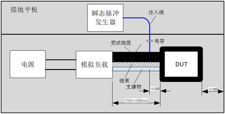
DCC method test arrangement (Compiled by: Zuo Chenggang)
3.6 Inductive coupling clamp (ICC) method
Inductive coupling clamp (ICC) is suitable for high current injection (BCI) probes, coupling the test pulses to the tested circuit, with no electrical connection to the DUT, wiring harness, or auxiliary equipment. The ICC method is suitable for coupling slow electrical transient test pulses, especially for DUTs with moderate or large numbers of tested cables..
The test arrangement for the ICC method is shown in the following diagram.
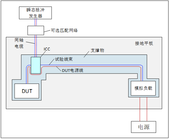
ICC method test arrangement (Compiled by: Zuo Chenggang)
The coupling circuit consists of an ICC that can clamp all signal wires. The DUT’s 12V/24V power lines (ground and power lines) should not be included in the ICC. Any other ground or power lines from the DUT to auxiliary equipment (sensors, actuators, etc.) should be included in the ICC. If the auxiliary equipment is grounded at the near end, the grounding connection should be excluded from the ICC. Any exceptions for grounding wires and power lines included in the ICC during testing should be specified in the test plan.
The test can be arranged as shown in the diagram, or according to the straight wiring harness arrangement specified in GB/T 33014.4.
When the DUT has multiple connectors, the test conditions (whether to test all connector wiring harnesses simultaneously or individually) should be specified in the test plan. The wiring harness should be placed on a non-conductive support 50mm above the grounding plate, with a tolerance of ±5mm. The length of the wiring harness should be1700+300mm. The center distance of the ICC should be(150±50)mm from the DUT connector.
3.7 Test summary
Relevant provisions for the transient immunity test of non-power lines in GB/T 33014.3 can be summarized as follows:
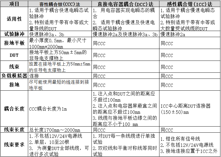
Transient immunity test for non-power lines directly (Source: Zuo Chenggang)
#04
Transient immunity coupled to non-power lines
The test facilities and equipment required for the electrical transient immunity testing of signal lines are shown in the following diagram (from a real DV report):
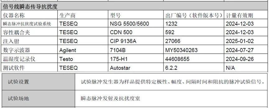
Transient immunity testing equipment for signal lines (Source: FQ Technology,CVC Weikai)
The test site is the same as for power line immunity tests, but the equipment used differs, including pulse immunity systems, capacitive coupling clamps, injection clamps, oscilloscopes, testing software, etc., consistent with the standard requirements.
4.1 DV test levels and requirements
In this DV test, the test levels, requirements, and determination standards for the DUT are as follows:
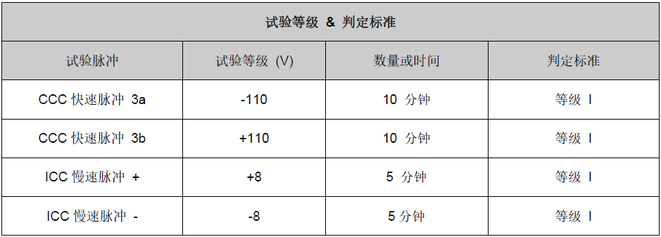
Transient immunity testing requirements for signal lines (Source: FQ Technology,CVC Weikai)
As seen in the diagram, the DUT underwent CCC and ICC tests, with CCC being fast pulses 3a and 3b, consistent with the specifications in the standard. Additionally, since the product has many wiring harnesses, it is also suitable for ICC method, which conducted slow pulse tests.
4.2 Arrangement of CCC method DV tests
According to the standard requirements, the arrangement of the CCC method test is shown in the following diagram:
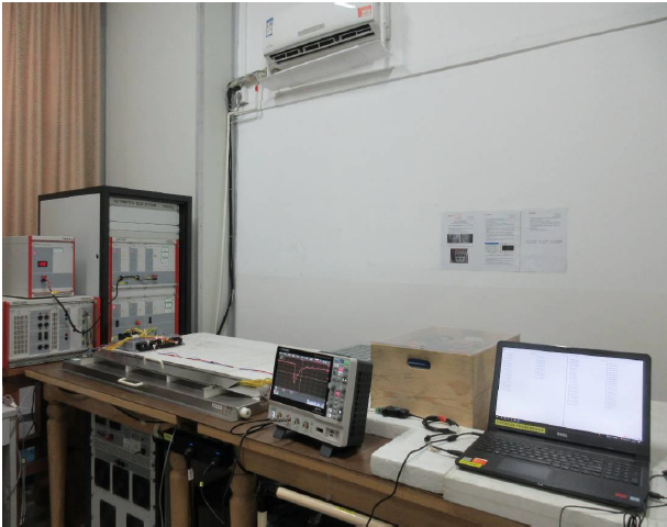
Overall test arrangement for CCC method (Source: FQ Technology,CVC Weikai)
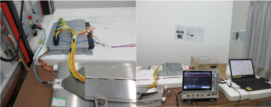
Partial test arrangement for CCC method (Source: FQ Technology,CVC Weikai)
As seen in the diagram, the test arrangement follows the standard requirements, where the CCC method pulse generator couples the test pulses to the DUT signal line, and the DUT connects to a simulated load.
4.3 Arrangement of ICC method DV tests
According to the standard requirements, the arrangement of the ICC method test is shown in the following diagram:
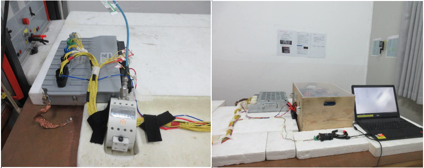
Overall test arrangement for ICC method (Source: FQ Technology,CVC Weikai)
Partial test arrangement for ICC method (Source: FQ Technology,CVC Weikai)
As seen in the diagram, the test arrangement follows the standard requirements, where the pulse generator applies the test pulses to the DUT signal line, and the DUT connects to a simulated load.
4.4 Result determination
The determination of test results is shown in the following diagram:
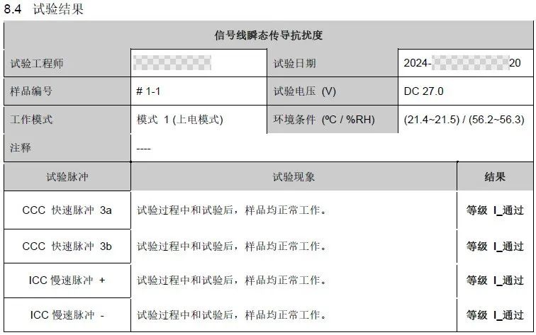
Test results and determination (Source: FQ Technology,CVC Weikai)
As seen in the diagram, the DUT’s operating mode during the test was mode1, with a test voltage of27V (the DUT is a 24V product), and the test results for each pulse met the test requirements.
This article mainly introducesGB/T 21437.2 standard regarding transient immunity along power lines andGB/T 21437.3 transient immunity of non-power lines, both of which fall under the category of conducted immunity. Thus, the entire introduction of the GB/T 21437 standard is complete, and what we will discuss next will only be the remaining topics of radiated immunity, bulk current injection(BCI) immunity and electrostatic discharge (ESD) immunity, all of which are part of the immunity section..
 / END /