This article is approximately 5,400 words long, recommended for saving and reading.
Author | Zuo Chenggang
Produced by | Automotive Electronics and Software
Introduction:
This article is the tenth piece in the series of articles titled “Automotive Grade Testing of ECUs” (click to view all articles).
Continuing from the previous articles, there is a lot of knowledge related to EMC, including standards and testing, which has been detailed in the previous articles regarding the testing standards for conducted and radiated emissions in GB/T 18655. This article will continue to introduce the GB/T 21437 standard, but GB/T 21437 is relatively complex, containing both conducted emission parts and content on immunity.
To facilitate understanding, following the ideas from the previous articles, the introduction of the standard will be categorized according to the dimensions of interference/ emission (disturbance) and immunity, and then explained step by step. All testing items in the text are accompanied by real DV testing photos, including testing equipment, samples, testing setups, testing limits, and result determinations, to help everyone gain a deeper understanding and recognition of DV testing.
*Note: Some content in this article is excerpted from the author’s new book “Reliability Design and Development Practice of General Automotive Grade Electronic Components“, published by the Machinery Industry Press in June 2024, with adaptations made during the excerpt. Due to the extensive content, it is recommended to save and read.The table of contents is as follows:
1. Overview of GB/T 21437 Standard
1.1 Introduction to GB/T 21437
1.2 Introduction to GB/T 21437.1
1.3 Introduction to GB/T 21437.1
2. Introduction to GB/T 21437.2
2.1 General Provisions
2.2 Classification of Functional Characteristic States
2.3 Functional Characteristic States
2.4 Artificial Network AN
3. Voltage Transient Emission Testing
3.1 Regulations on Transient Conducted Emission Testing
3.2 Test Arrangement
3.3 Limit Assessment
4. Voltage Transient Emission DV Testing
4.1 DV Testing Requirements
4.2 DV Test Arrangement
4.3 DV Test Limits and Result Determination
#01Overview of GB/T 21437 Standard
1.1 Introduction to GB/T 21437
GB/T 21437 standard consists of three parts, the latest standards are:
-
GB/T 21437.1-2021: Part 1: Definitions and General Provisions
-
GB/T 21437.2-2021: Part 2: Electrical Transient Conducted Emission and Immunity along Power Lines
-
GB/T 21437.3-2021: Part 3: Immunity to Coupled Electrical Transients on Non-Power Lines
GB/T 21437 is a complex standard, and those unfamiliar with it may easily become confused. Unlike the previously discussed GB/T 18655 standard, which is entirely about interference/ emissions, GB/T 21437 includes both interference/ emissions and immunity. This is particularly evident in the second part of the standard GB/T 21437.2, where the first part discusses transient conducted emissions, and the latter part discusses immunity, while GB/T 21437.3 covers immunity entirely, which can easily confuse those encountering this standard for the first time. To aid in differentiation and understanding, the following diagram is provided again:
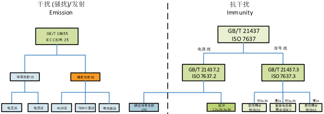
EMC Interference Related Standards (Source: Zuo Chenggang “General Automotive Grade”)
1.2 Introduction to GB/T 21437.1
Here, I will briefly introduce the introduction section of the standard:
Vehicles generate electrical and radio frequency disturbances during normal operation. These disturbance signals have a wide frequency range and can affect onboard electrical/ electronic components and systems through conduction, coupling, or radiation. In recent years, vehicles have been extensively equipped with electrical/ electronic components and systems for various functions such as control, monitoring, and display, which are susceptible to disturbances generated by the vehicle’s own electrical/ electronic systems (e.g., ignition systems, generators/ alternator systems, motors, and actuators, etc.) leading to performance degradation (temporary failures, or even permanent damage).
GB/T 21437 “Road Vehicles – Electrical/ Electronic Components – Test Methods for Conducted and Coupled Electrical Disturbances” aims to establish test methods for electrical transient conducted emissions and immunity for electrical/ electronic components used in road vehicles, and is intended to consist of five parts.
-
Part 1: Definitions and General Provisions. The purpose is to define terms and definitions, test conditions, classification of functional characteristic states, etc.
-
Part 2: Electrical Transient Conducted Emission and Immunity along Power Lines. The purpose is to specify the test equipment, test methods, and requirements for electrical transient conducted emission and immunity tests along power lines.
-
Part 3: Immunity to Coupled Electrical Transients on Non-Power Lines. The purpose is to specify the test methods for immunity to coupled electrical transient pulses on non-power lines.
-
Part 4: Electrical Transient Conducted Emission and Immunity along Shielded High Voltage Power Lines. The purpose is to specify the test methods for electrical transient conducted emissions along shielded high voltage power lines.
-
Part 5: Supplementary Methods for Pulse Generators and Verification. The purpose is to ensure that test results are comparable and repeatable.
However, currently, only the first three parts and the standard’s 1-3 have been published, as shown in the following diagram:
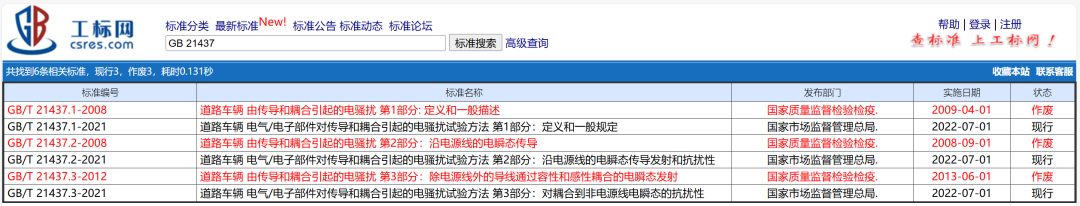
Implementation Status of GB/T 21437 Standard (Source: National Standard Network)
1.3 Introduction to GB/T 21437.1
GB/T 21437.1 is the first part of the standard: Definitions and General Provisions, GB/T 21437.1 specifies the main characteristics of the test methods in the relevant parts of the standard as shown in the table below:
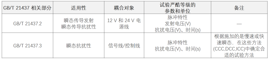
Main Characteristics of Test Methods in GB/T 21437 (Compiled by Zuo Chenggang)
The main difference between the second and third parts of the standard is that the second part specifies conducted emissions and immunity along power lines, while the third part addresses immunity on non-power lines (i.e., signal or control lines). In other words, only GB/T 21437 has a part of GB/T 21437.2 that is about interference/ emissions, while the other parts are all about immunity.
GB/T 21437.1 specifies the following parameters for supply voltage, temperature, etc.:
-
Duration and distance, tolerance ±10%;
-
Resistance and impedance, tolerance ±10%.
-
Test temperature: The ambient temperature during the test should be (23±5)℃.
-
Test voltage: The supply voltage during the test is:
-
12V electrical system: (13±1)V;
-
24V electrical system: (26±2)V.
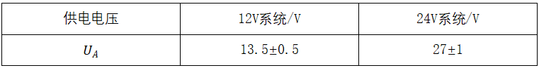
In GB/T 21437.2, the specifications for test voltage are slightly different, as follows:
-
12V electrical system: (13.5±0.5)V;
-
24V electrical system: (27±1)V.
#02
Introduction to GB/T 21437.2
The standard for conducted emissions along power lines is GB/T 21437.2, which is the second part of the standard: Electrical Transient Conducted Emission and Immunity along Power Lines. Some test methods in the standard require the use of artificial networks to ensure comparability between results from different laboratories. The standard specifically states that the electrical transient immunity bench test along power lines uses a test pulse generator method, where the described test pulse is only a typical pulse form and does not cover all possible transients that may occur in vehicles. Users of the standard can determine whether to specify and apply additional test pulses based on the function or connection status of the electrical/ electronic components.
2.1 General Provisions
Test temperature: During the test, the surrounding ambient temperature should be (23±5)℃.
Test voltage: The supply voltage U A should be measured at the output of the pulse generator and should comply with the specifications in the table below. If other values are used, they should be noted in the test report.
2.2 Classification of Functional Characteristic States
Classification of functional characteristic states is based on GB/T 33014.1-2016 (Road Vehicles – Electrical/ Electronic Components – Test Methods for Immunity to Narrowband Radiated Electromagnetic Energy – Part 1: General Provisions) Appendix A,
Functional characteristic state classification (FPSC) considers the following factors:
a) An ESA may include one or more functions (for example, an ECU may control the front wiper, step lighting, low beam lights);
b) A function may have one or more operating modes (for example, low beam lights ON, low beam lights OFF, step lights ON, step lights OFF);
c) An operating mode may have several states (I, II, III, IV) (for example, in the low beam lights ON operating mode, the low beam lights may turn OFF during disturbance application, and be able to automatically recover after the disturbance stops, which is considered state II).
The FPSC method is based on the following principles:
-
When a DUT includes multiple functions, the functional characteristic state classification applies to each independent function;
-
A function may have simple ON-OFF operating modes or complex operating modes similar to data bus communication.
2.3 Functional Characteristic States
Functional characteristic states define the expected objectives of the functional characteristics of the DUT in the test environment, suitable for each independent function of the DUT, describing the expected operational states during and after the test. The following are four functional characteristic states:
-
State I: Able to complete the designed function during and after the test.
-
State II: Unable to complete the designed function during the test, but able to automatically recover to normal state after the test.
-
State III: Unable to complete the designed function during the test, and unable to recover to normal state without simple operation by the driver/passenger after the test, such as turning the DUT off/on, or restarting the ignition switch.
-
State IV: Unable to complete the designed function during the test, and requires more complex operations to recover to normal state after the test, without causing any permanent damage to the DUT’s function. For example, disconnecting the battery or power supply and then reconnecting.
2.4 Artificial Network AN
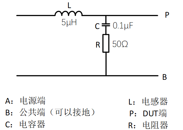
Here, I will also briefly introduce the artificial network (Artificial Network, AN), which is different from the artificial mains network (Artificial Mains Network, AMN). The artificial network replaces the impedance of the vehicle wiring harness and serves as a reference standard for impedance in the laboratory to determine the performance of devices and electrical/ electronic devices. GB/T 21437.2 has similar provisions for artificial mains networks as GB/T 18655, but is not as detailed. The following diagram illustrates the principle of the artificial network.
Provisions for Artificial Networks in GB/T 21437.2 (Compiled by Zuo Chenggang)
Artificial networks should be able to withstand continuous loads consistent with the requirements of the DUT. The following diagram shows the impedance value measured between points P and B when terminals A and B are shorted under ideal electrical components. In practice, the impedance of the artificial network should not deviate more than 10% from the curve shown in the diagram below.
The main characteristics of various components of the artificial network are as follows::
-
L=5μH (hollow coil)
-
Internal resistance between points P and A:<5mΩ
-
C=0.1μF, capable of withstanding AC 200V, DC 1500V
-
Resistance R=50Ω
The impedance frequency curve of the artificial network is shown in the diagram below:
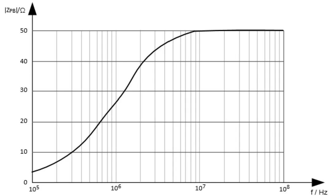
Impedance Frequency Characteristics Curve of the Artificial Network (Compiled by Zuo Chenggang)
#03
Voltage Transient Emission Testing
For electrical/ electronic components that are potential sources of conducted disturbances, transient conducted emission testing should be performed.
3.1 Regulations on Transient Conducted Emission Testing
This test applies to DUTs containing inductive loads or driving inductive loads through mechanical or electronic switches (DUT). For example, electric windows, electric seats, relays, electric mirrors, etc., connected to the vehicle power supply, with large inductance or high inductive load currents. If the inductance of the inductive load is small or the current is low, and is driven by an internally stabilized voltage (e.g., 5V) and isolated from the vehicle power supply, this test does not apply, and the test plan specifies exceptions. From this regulation, it can be seen that standard users need to confirm the applicability of this test standard when formulating DVP. For onboard electronic modules, apart from ECUs that directly control larger inductive loads, other electronic modules in systems such as audio-visual entertainment systems, intelligent driving systems, etc., may not be applicable to this test, which needs to be analyzed and confirmed based on the product type.
During the test, measures should be taken to ensure that the measurement arrangement is not disturbed by the surrounding electromagnetic environment, so this test is usually conducted in a shielded room.
To measure the voltage transients generated by the disturbance source, a standard impedance artificial network should be used (as shown in the diagram below). All connections between the artificial network, switches, and the DUT should be placed above a metal grounding plate at a height of 50mm ± 5mm. The cable specifications should be selected according to the actual usage conditions of the vehicle, and the wiring should be able to withstand the operating current of the DUT, and should be determined after agreement between the vehicle manufacturer and supplier.
The grounding method of the DUT should consider the actual installation in the vehicle and be defined in the test plan. If the test plan does not specify, the DUT should be placed on a non-conductive material above the grounding plate at a height of 50mm ± 5mm.
The standard requires the use of voltage probes and oscilloscopes or waveform acquisition devices to measure the supply voltage and disturbance voltage, with voltage waveform parameters specified in Appendix B of the standard. The testing requirements are as follows:
1) During measurement, the DUT should be tested under various different operating modes. The test conditions for the DUT should be specified in the test plan.
2) Appropriate sampling rates and trigger levels should be selected, to obtain complete transient waveforms. Sufficient resolution should be selected to display the maximum positive and negative values of the transients.
3) Appropriate sampling rates and trigger levels should be selected, and the DUT should be operated according to the test plan, recording the voltage amplitude. Other transient parameters, such as rise time, fall time, duration width, etc., should also be recorded.
4) Unless otherwise specified, at least 10 waveforms should be collected, recording waveforms that include maximum positive and negative amplitudes and their related parameters.
3.2 Test Arrangement
The voltage transient emission test arrangement needs to be divided according to the type of test, which is divided into the following three types:
1) Slow Pulse Test Arrangement: The DUT has an internal switch. Measurement requirements are to measure the transients generated when the DUT power is disconnected, measured when switch S is turned off (operating switch S to generate transient disturbances).
2) Fast Pulse Test Arrangement: The DUT has no internal switch. The test generates transient disturbances by disconnecting the DUT power, meaning that measurements are taken when switch S is turned off (operating switch S to generate transient disturbances).
3) Fast Pulse Test Arrangement: The DUT has an internal switch. The test generates transient disturbances by operating the internal switch (no external switch is needed). When the internal switch is turned off (operating the switch generates transient disturbances), the transients generated when the DUT power is disconnected are measured, with the probe as close as possible to the DUT terminal.
The standard has three arrangement diagrams, and I will briefly introduce them, divided into arrangements with and without internal switches for the DUT, as shown below:
Voltage Transient Emission Test Arrangement – DUT with Internal Switch (Compiled by Zuo Chenggang)
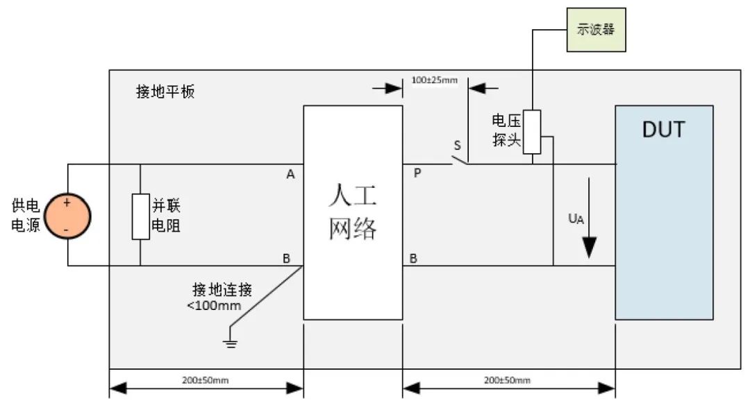
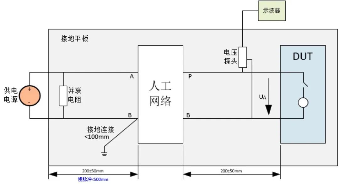
Voltage Transient Emission Test Arrangement – DUT with External Switch (Compiled by Zuo Chenggang)
As can be seen from the above diagrams, the DUT acts as a disturbance source, connected to parallel resistors and the power supply through the artificial network, with the distance from the DUT to the artificial network being 200±50mm, and the distance from the artificial network to the power supply being 200±50mm (for slow pulse tests, it is < 500mm).
3.3 Limit Assessment
Limit assessment for transient emissions is placed in Appendix B of the standard, which provides a series of parameters to consider for evaluating waveform characteristics, such as: peak amplitude, pulse width, pulse rise time, pulse fall time, pulse repetition time, surge width, surge interval time, surge cycle time, etc.
The minimum and maximum limits for transient emissions are divided into 5 levels, as shown in the table below. According to the testing requirements, these values or acceptable limits between these values can be selected. During evaluation, any parameter in the table may be required to be met, or all parameter requirements may be met according to the agreement. In the absence of specific values, it is recommended to select levels from level I to level IV.
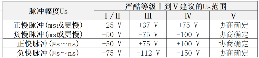
Transient Emission Waveform Severity Levels (Compiled by Zuo Chenggang)
#04
Voltage Transient Emission DV Testing
As mentioned above, the scope of the voltage transient emission test is limited. I found a previously conducted DV report and extracted some content from it to help everyone understand and familiarize themselves with this test.
The standard requires that conducted emissions – voltage method DV testing must be conducted in a shielded room, and the required testing facilities and equipment are shown in the diagram below (from a real DV report):
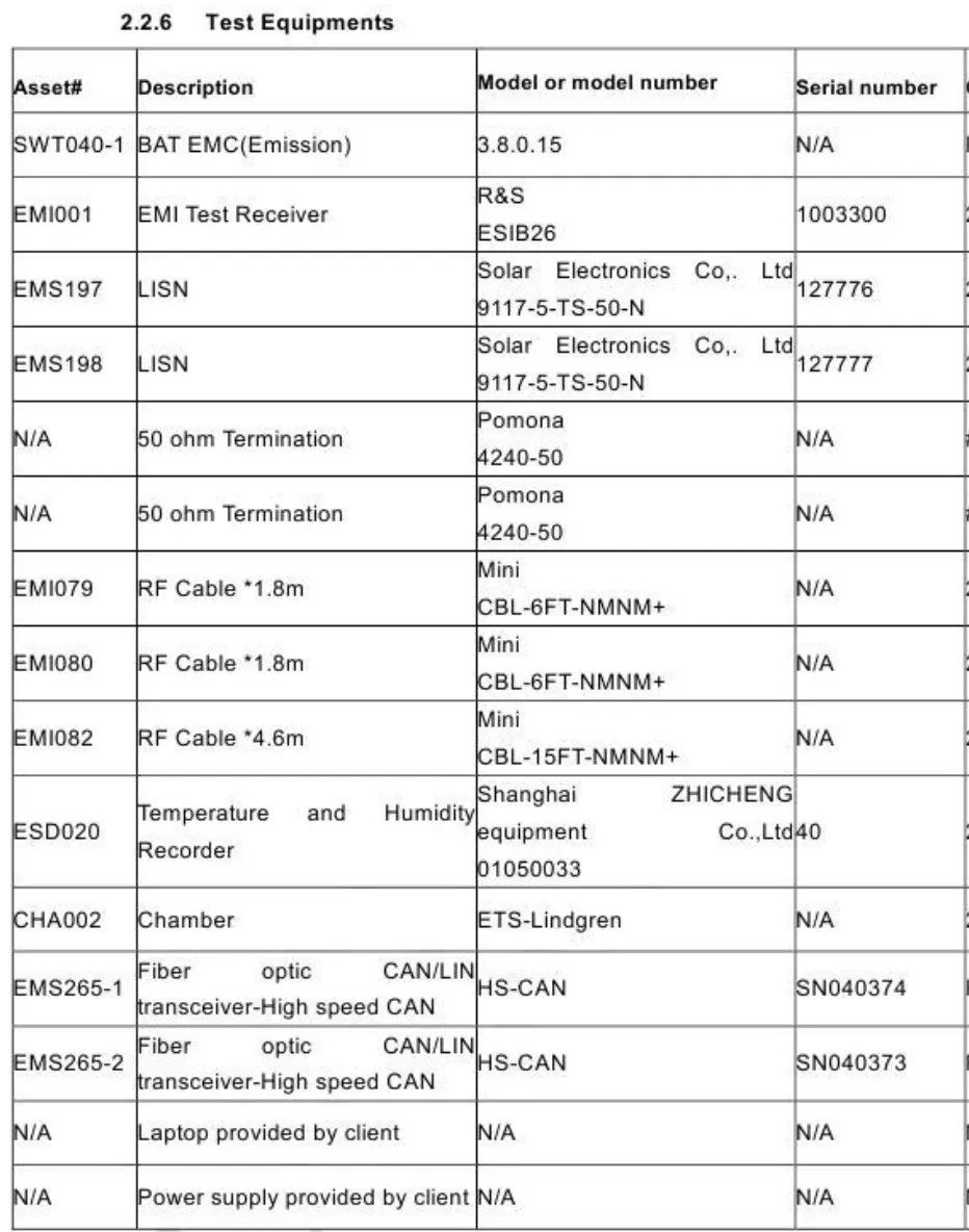
Voltage Transient Emission DV Testing Equipment (Source: Zuo Chenggang)
As can be seen from the above diagram, the test is conducted in an electromagnetic shielded room, and the testing requires the use of artificial power networks, EMI testing receivers, and other equipment, which is consistent with the standard requirements.
4.1 DV Testing Requirements
The DV report will detail the testing requirements for voltage transient emissions. As shown in the diagram below, the testing is conducted in a shielded room, and other test arrangements are also in accordance with standard requirements. From the diagram, it can be seen that the DUT is a 12V system component, arranged according to an external switch.
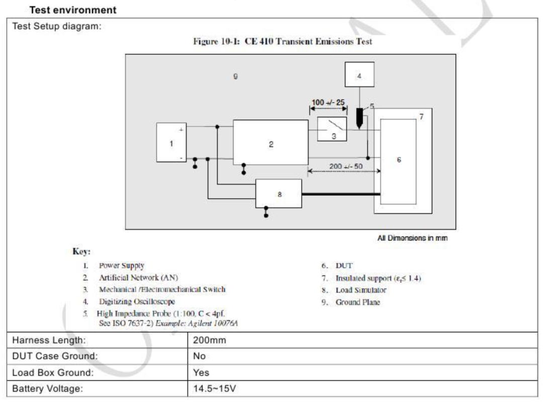
Testing Requirements for Voltage Transient Emissions (Source: Zuo Chenggang)
4.2 DV Test Arrangement
The actual voltage transient emission DV test arrangement is shown in the diagram below:
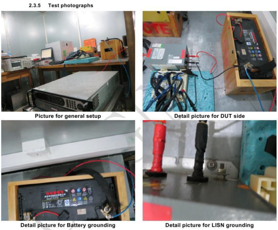
Voltage Transient Emission DV Test Arrangement (Source: Zuo Chenggang)
4.3 DV Test Limits and Result Determination
In this DV testing requirement, the disturbance emission limit for the DUT is as shown in the table below, and the test results indicate that the limit requirements can be met.
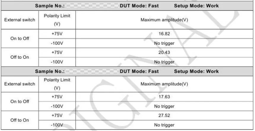
Limit Requirements and Test Results for Voltage Transient Emissions (Source: Zuo Chenggang)
The minimum and maximum limit waveforms for transient emissions are shown in the diagram below;
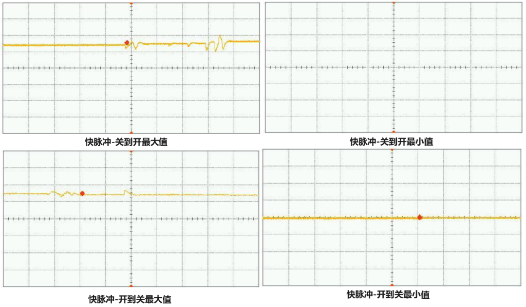
Test Waveforms for Voltage Transient Emissions (Source: Zuo Chenggang)
Due to space limitations, this article provides a preliminary introduction to the first and second parts of the GB/T 21437 standard, including an overview of the standard, classification of functional characteristic states, and voltage transient emission standards and DV testing. The next articles will continue to introduce the second part of the GB/T 21437 standard regarding immunity. Thus, all standards and tests related to interference/ emissions have been fully discussed, and the next topics will all be about immunity. Let us briefly review the standards related to interference/ emissions:
-
The GB/T 18655 standard includes: Conducted Emission Voltage Method, Conducted Emission Current Probe Method, Radiated Emission ALSE Method.
-
The GB/T 21437.2 standard includes the section on voltage transient emissions.
The section on transient immunity (both power and non-power lines) in the GB/T 21437 standard will be detailed in the upcoming articles, so stay tuned.
 / END /