The initialization of the stack pointer and PC pointer through the reset vector after power-on reset on ARMv7, followed by a jump to the assembly entry to begin system initialization and other operations, is crucial for embedded system software development. Although different SoCs may have variations in the address allocation of BootROM and Flash, the overall process from reset to normal program startup is generally consistent.
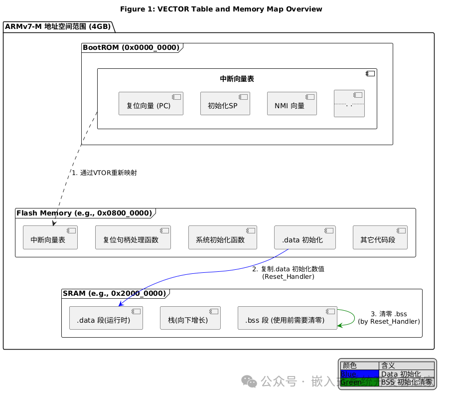
The above figure describes the definition, storage location, and key remapping mechanism of the interrupt vector table in the ARMv7-M architecture (commonly used in Cortex-M series processors). The core workflow can be divided into the following parts:
1. Physical Storage and Logical Mapping
There are two key copies of the interrupt vector table in the system:
Physical Storage Location (Flash): The interrupt vector table is typically permanently burned into the starting position of non-volatile memory (Flash), such as 0x0800_0000. The interrupt vector table component in the Flash Memory area in the figure represents this physical copy.
Logical Mapping Address (BootROM): However, the ARM architecture specifies that the CPU will fetch the initial value of the Main Stack Pointer (MSP) and the reset exception vector from address 0x0000_0000 after power-on or reset. The interrupt vector table component within the BootROM framework in the figure represents this logical address space.
2. Remapping Mechanism (VTOR)
These two address spaces do not initially overlap. To address this issue, ARMv7-M introduces the Vector Table Offset Register (VTOR).
Boot Phase: During the early startup of the chip, the hardware may automatically map the Flash physical address (0x0800_0000) to the logical address (0x0000_0000), allowing the CPU to correctly read the vector table stored in Flash. This is a simple hardware remapping.
Runtime Phase: After software initialization, the logical address of the interrupt vector table can be directly pointed to the physical storage address (i.e., 0x0800_0000) by configuring the VTOR register. The dashed arrow in the figure visually represents this process of remapping through VTOR. Once remapping is complete, all subsequent interrupts will be handled by the CPU based on the address pointed to by VTOR (the physical vector table in Flash).
3. Initialization Process
The reset vector in the figure points to the reset handler function, which is the first program executed after the system starts and is responsible for critical initialization operations:
.data Segment Initialization: Copies the initial values of initialized global and static variables from Flash (DATA_init) to their runtime locations in SRAM (DATA_runtime), as indicated by the blue arrow.
.bss Segment Zeroing: Zeros out the memory area (BSS) where uninitialized global and static variables reside, as indicated by the green arrow.
Stack Initialization: Sets the Main Stack Pointer using the value from the first entry “Initialize SP” in the vector table, as suggested by the hidden line indicating the source of the initial stack pointer value from the vector table.
Summary
The interrupt vector table is physically stored in Flash, but through the VTOR remapping mechanism, it can logically respond to the CPU’s request to access the interrupt vector starting from address 0x0000_0000. The reset exception serves as the trigger for the startup process, and its service function not only guides the program to jump to the main application but also undertakes the critical task of completing data segment initialization and preparing for the C language runtime environment.