As chips become larger, the number of IPs integrated on SOC, whether hard IP or soft IP, is increasing. The testing of these IPs is crucial for the entire chip, which is why the IEEE 1687 protocol has emerged. I believe that the 1687 protocol is an upgrade to 1149.1 and 1500. Compared to them, 1687 has the following characteristics:
-
Portability. By utilizing 1687, plug and play can be achieved to some extent. Before the 1687 protocol, testing an IP required manually describing it, configuring TDR, and assigning instructions based on the corresponding databook. With the 1687 protocol, we have predefined the boundary information of the IP and integrated patterns. When we receive an IP, DFT engineers can be provided with the IP’s ICL and PDL, allowing tools to easily obtain the testing information related to this IP, which is very beneficial for system integration.
-
Tradeoffs. The concept of a network is introduced in 1687. Compared to 1149.1, some compromises have been made in terms of access time and network management, making it more user-friendly for Physical Design or tools to regenerate patterns.
-
Retargeting. When we use a bottom-up approach for DFT design, after inserting DFT logic at the lower level, tools can generate the corresponding ICL and PDL for this IP, which can then be directly applied to the top-level design.
The 1687 protocol consists of three parts:
-
Network. We can flexibly configure IP testing through the TDR serial link.
-
ICL (Instrument Connectivity Language). ICL is a network description language for IJTAG. Just as IEEE defines the use of Verilog or VHDL to describe circuit construction, we use ICL to describe the aforementioned Network itself.
-
PDL (Procedural Description Language). PDL is the relevant information provided by IP designers to DFT engineers or Pattern Generation board debugging engineers. After the tools read it, they can automatically obtain the testing information related to this IP.
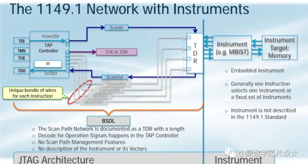
Before introducing the 1687 protocol, let’s briefly introduce the 1149.1 protocol. As shown in the figure below:
For 1149.1, if we want to control an IP, for example, the Instrument shown in the figure is an Mbist, this IP has a corresponding TDR that needs to be connected to the TAP Controller. We can see that the connection of this Network is straightforward; each TDR has its own set of signals diverging from the TAP Controller to various IPs. Therefore, the Network in 1149.1 is very simple and clear, with all signals diverging from the TAP Controller to each TDR. In 1149.1, the connections of the Network and Boundary Scan-related information are described through BSDL files.
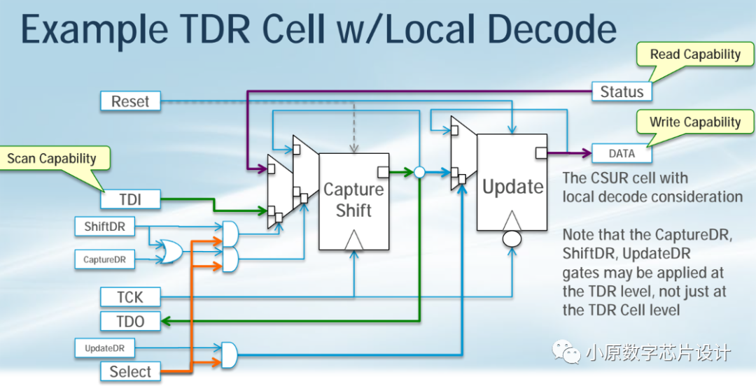
Based on the description of 1149.1, we know that the TAP Controller sends a multitude of signals to control each dedicated TDR. Is it possible to transform these signals into local control? Thus, we introduce the CSUR (Capture Shift Update Register) structure shown in the figure below. First, it can achieve shift capability through ShiftDR, TDI, and TDO. Secondly, it can achieve read capability; when the TAP Controller needs to sense the status of an IP, the status enters the Capture Shift Register through enabling CaptureDR and is latched, then switched to ShiftDR to achieve read. The last function is write; when TCK toggles, data continuously flows in TDI and TDO, changing all the time. When the data flows to a certain point, this value is what we want to give to the IP, at which point we stop the shift and trigger an UpdateDR, making this value a fixed value for the IP. From the above description, we can see that compared to the definition in 1149.1, all ShiftDR, CaptureDR, and UpdateDR have become global signals. The difference is that we have added a Select signal; only when this TDR is truly selected will these signal values be passed into CSDR.
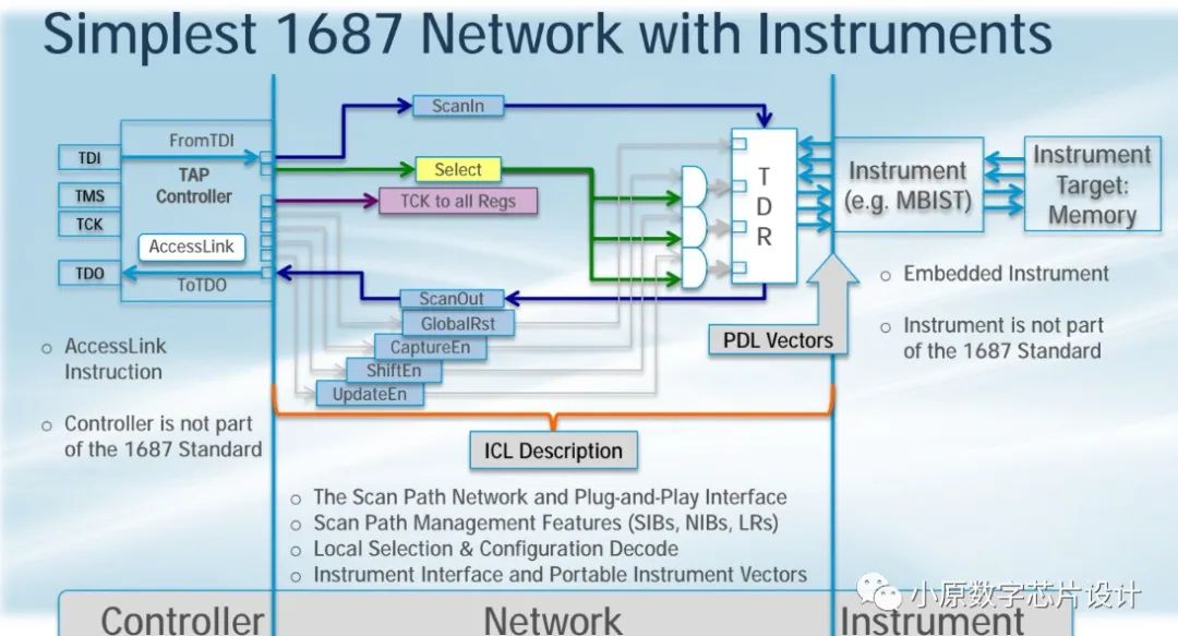
From the figure below, we can see that compared to 1149.1, in 1687, we only need to broadcast global control signals to each TDR and then select through local Select. Returning to the 1687 protocol itself, the Network can be described through the ICL protocol, and how to control the TDR to enable the Instrument to perform certain functions can be described through PDL. The 1687 protocol does not define how the TAP Controller is implemented; it is generally recommended to use the 1149.1 TAP Controller, with the Instrument designed by the IP to perform certain functions, and then pass a PDL Vector to describe how to control the IP to achieve certain functions.
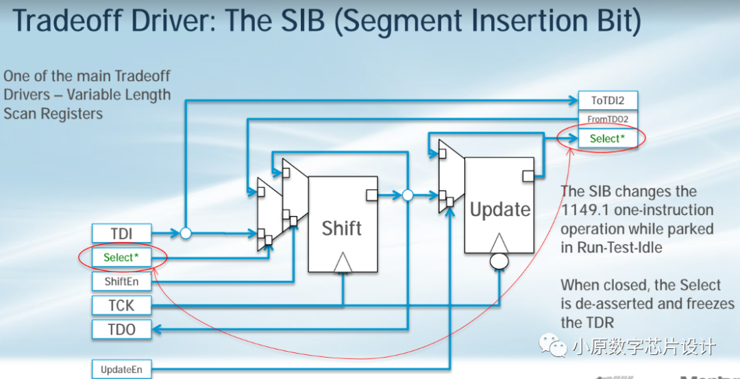
Based on the analysis of the above figure, 1149.1 and 1687 are very similar. However, if 1687 only made the improvements mentioned above, the Network function itself would not be fully utilized. Therefore, we need to introduce the structure shown in the figure below (SIB) to realize the powerful network structure of 1687. The SIB can be likened to a combination of switches and routers, allowing for flexible network scaling. When I turn off a certain SIB, all the IPs or TDRs connected behind this SIB are turned off, but the Network itself can still function.
In summary, we have briefly introduced the basic concepts and components of the 1687 protocol. In the next section, we will specifically introduce the SIB network structure and the specific structure of SIB in Mentor Tessent.