
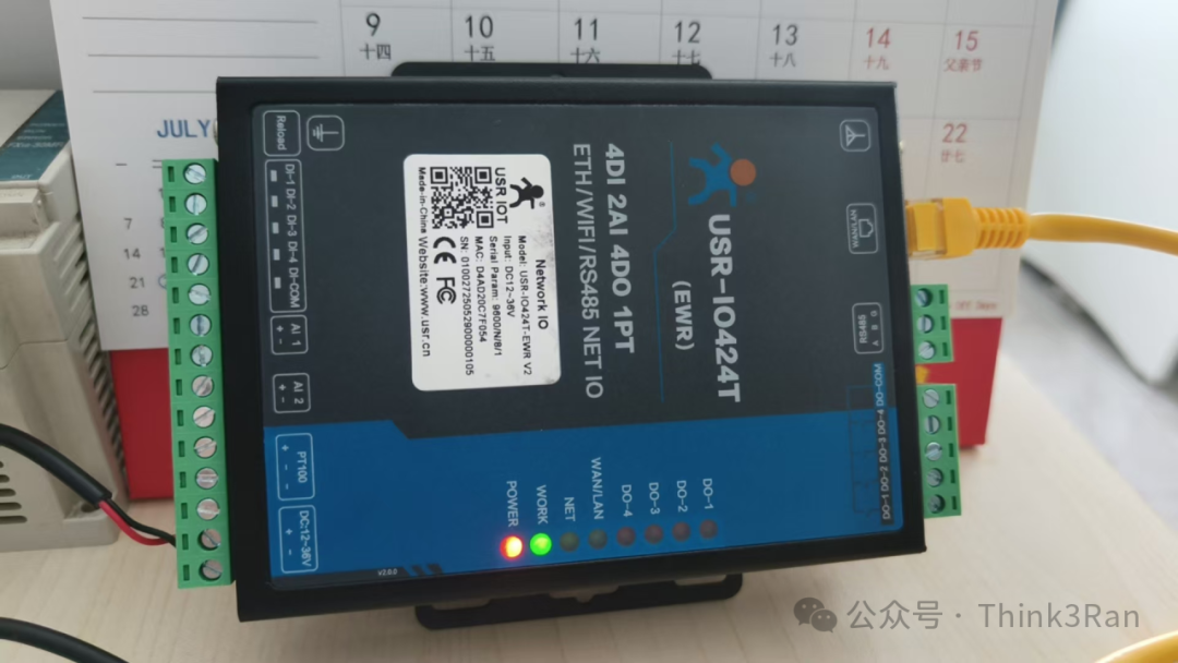
Product Introduction
The IoT IO controller is commonly used for remote control, signal conversion, achieving network to IO, controlling IO, collecting IO, and AI voltage functionalities. This article shares practical experiences using the USR-IO 424 IoT IO controller as an example of this type of product.

Application Scenarios
1. Cloud control system provided by the manufacturer.
2. Local area network control, which is the most commonly used, can connect to wired or wireless WiFi networks for control.
3. Serial connection, which can be used for conversion control.
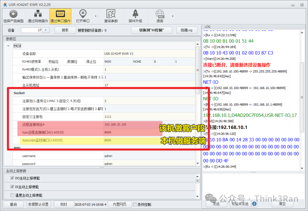
Parameter Settings (Initial Debugging)
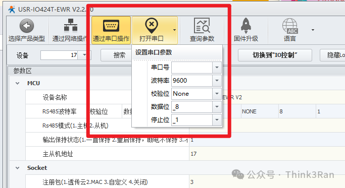
Settings can be configured using software on a PC or the default web page provided by the device. As shown in the figure below.
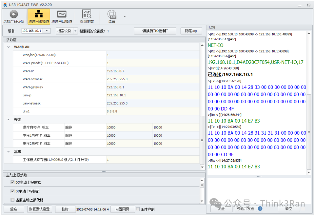
The default port for the PC software to search for broadcasts is 48899. If this port is occupied, it may result in connection issues.

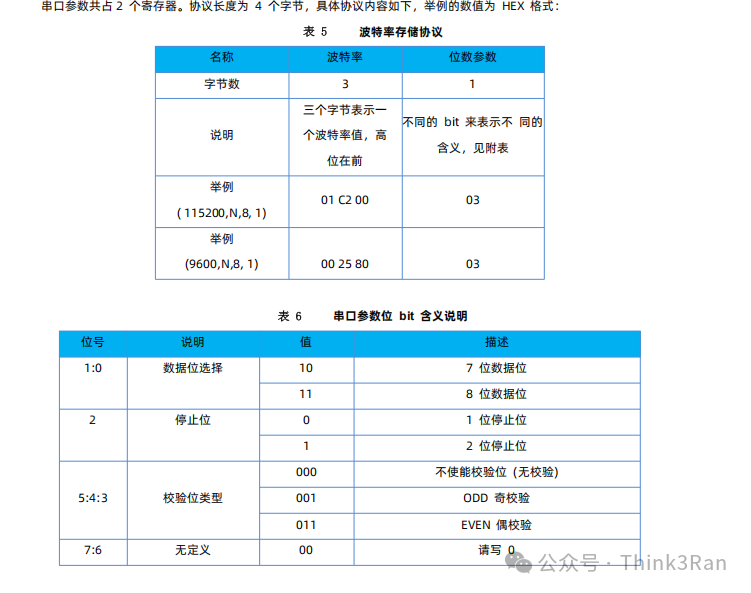
There is also a serial mode for connection. The default communication format is N81:
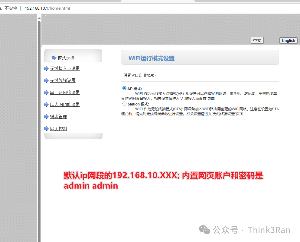
Network and WiFi Settings
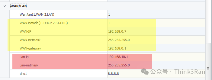
This network port can be either a WAN or LAN port, primarily serving as either a sender or receiver, accessible within the same network segment. In our application scenario, we generally set the LAN port to control this module, manually filling in the IP address, with the default being the WAN port for adjustments.
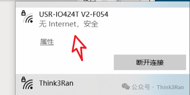
WiFi also corresponds to this functionality:
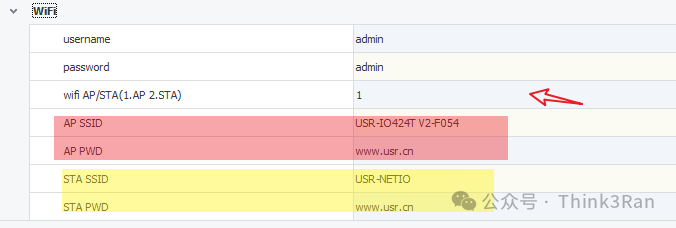
Therefore, we can perform operations based on the actual application scenario. One option is to set the WAN port to AP mode, allowing us to connect to the device’s own IP to adjust its parameters. The other option is to set it to LAN mode corresponding to STA mode.
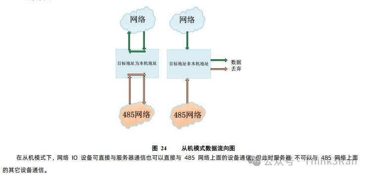
Operating Modes
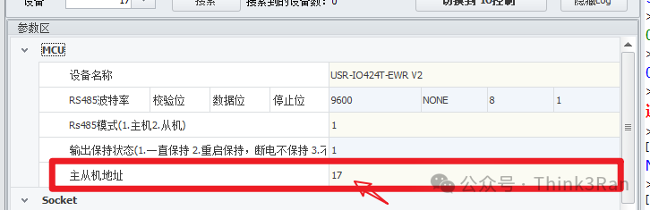
This device follows the Modbus RTU protocol and can be set to master mode, allowing for the expansion of multiple external devices. The factory default is slave mode, which only accepts data packets addressed to itself.
Data Packet Communication Uses Socket Protocol
Using Socket, it can act as both a client and a server. Once connected, the NEN light will illuminate.
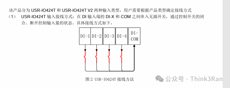
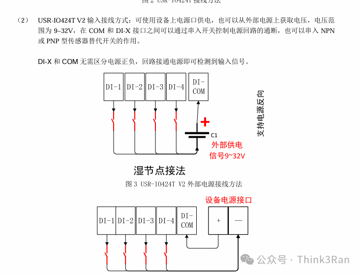
Wiring
1. Input wiring DI:
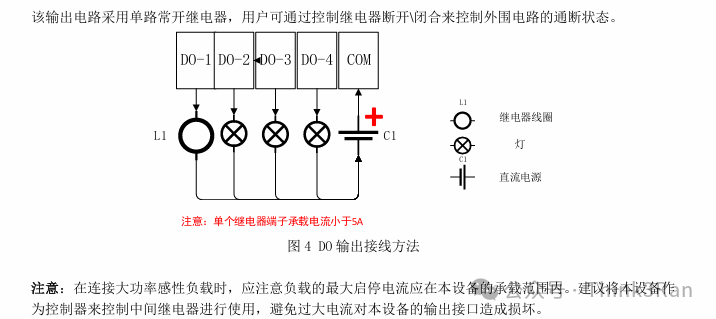
2. Output wiring DO:
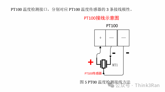
3. Temperature detection wiring:
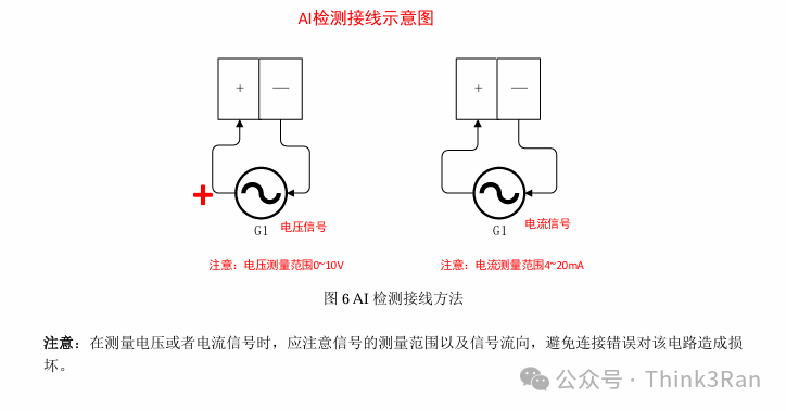
4. Current detection wiring:
Function Command Description
The device communication follows the Modbus RTU communication format:
Format:

Address + Function Code + Address + Register Value + Checksum (all high byte first)
The default address starts at 1, which is 0x01 in hexadecimal.
Specific usage is divided according to function codes:
01
0x01 Read Coil Register Function Code (Output Signal)
Assuming slave address 11 with default value for testing, the test output values for 4 channels are:
11 01 00 00 00 01 FF 5A
11 01 00 01 00 01
11 01 00 02 00 01
11 01 00 03 00 01
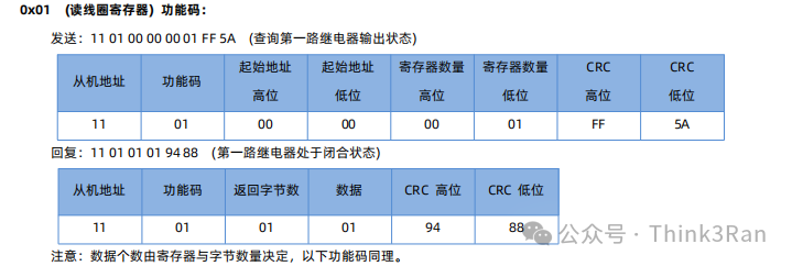
The result shows that if the fourth data bit is 1, there is an output.
02
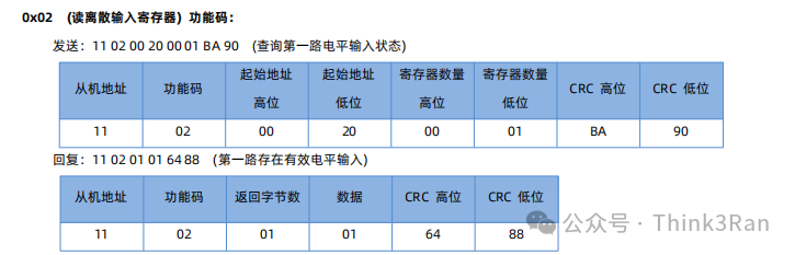
0x02 Read Discrete Input Register Function Code (Read Input Signal)
Assuming slave address 11 with default value for testing, the test input values for 4 channels are:
11 02 00 20 00 01 BA 90
11 02 00 21 00 01
11 02 00 21 00 01
11 02 00 21 00 01
03
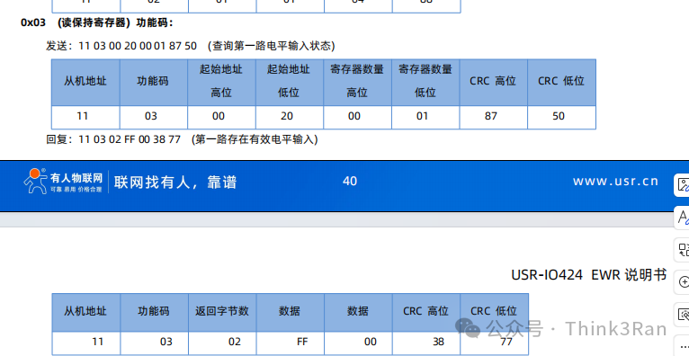
0x03 Read Holding Register Value
This is not commonly used:
04
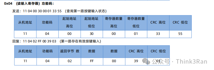
0x04 Read Input Register Function Code, used for checking buttons
05
0x05 Write Single Coil Register Value, commonly used
Assuming slave address 11 with default value for testing, the output values for 4 channels are:
To close the first output, the command is:
11 05 00 00 FF 00 8E AA
To open the first switch, the command is:
11 05 00 00 00 00 CF 5A
To close the second output, the command is:
11 05 00 01 FF 00 DF 6A
To open the second switch, the command is:
11 05 00 01 00 00 9E9A
To close the third output, the command is:
11 05 00 02 FF 00 2F 6A
To open the third switch, the command is:
11 05 00 02 00 00 6E 9A
To close the fourth output, the command is:
11 05 00 03 FF 00 7E AA
To open the fourth switch, the command is:
11 05 00 03 00 00 3F 5A
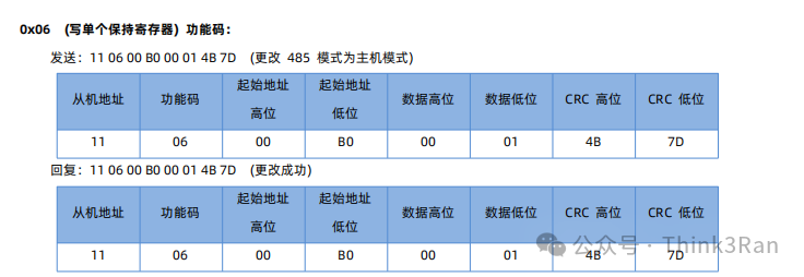
06
0x06 Write Single Holding Register Function Code
07
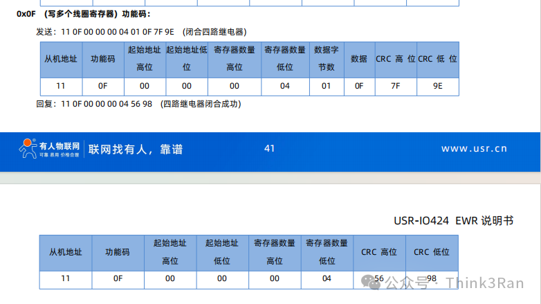
0x0F Write Multiple Coil Register Function Code
08
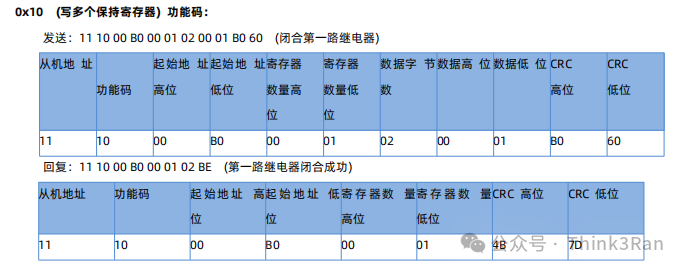
0x10 Write Multiple Holding Registers
03
Function Address Allocation as Follows:
1. The base address of the register is 0x0000.
2. In the register table, MCU parameters and communication module parameters must be block operated and cannot be split.
3. The accompanying software USR-IO uses UTF-8 encoding format.
4. Registers store hexadecimal data; whatever is written is what is read.

Other parameters can be found in the manual. The checksum is calculated using Modbus RTU, with the high byte first. CRC check.
Product Usage Precautions
1. To restore factory settings, press the button at the bottom for 3 seconds, then power off and restart to restore factory settings.
2. To make the communication parameters and categories effective, a power off and restart is required.
3.