
Click the aboveblue text, send it to your friends, and share more information😉
Photography can bring a lot of joy to work, study, and life. Often, it is necessary to record the challenges encountered during work or experiments, and a camera can capture the moment. In learning, there are times when quick documentation of materials is needed, and a camera can be very useful. The author has a Sony DXC-HX300 camera that can be equipped with a shutter release cable (as opposed to mechanical or pneumatic shutters). When gathering with friends, taking group photos with the camera often requires the photographer to be present, and using the camera’s self-timer feels too short at 2 seconds, while 10 seconds is too long, making it difficult to capture everyone’s expressions. The limited length of the shutter release cable does not solve the problem. How can this contradiction be resolved? The author thought of adding a remote control function to the camera, allowing the photographer to control it at any time. Based on this idea, let’s get started.
First, open the shutter release handle to check the internal structure. Contrary to the initial assumption that it is just a simple switch, the structure is shown in Photo 1.
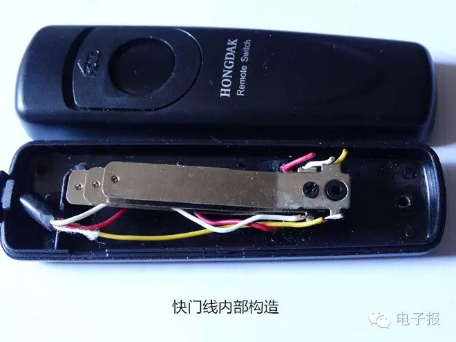
Photo 1 consists of three spring pieces, thus there are three leads connected to the camera. Measurements with a multimeter show that in the half-press state, the top two spring pieces first connect the yellow and white wires, corresponding to the camera function of quickly focusing and framing. When fully pressed, the shutter is automatically opened, and the speed depends on the camera settings. In this state, all three spring pieces are conductive. The entire process is that the yellow and white wires connect first, followed by the yellow, white, and red wires. To clarify the relationship between the three spring pieces, I experimented to see if the shutter could be opened using only two spring pieces. I connected additional wires corresponding to the original three wires and found that without pressing the shutter release button, short-circuiting the new yellow-red or white-red wires could not open the shutter. It is necessary to short-circuit the yellow, white, and red wires together to open the camera shutter; all three are essential, and the order cannot be reversed. With this information, I began circuit design. Remote control can be achieved through various means such as light, sound, ultrasound, infrared, or radio. In outdoor environments, wireless remote control is preferable. Once the method was determined, I began assembling the circuit. I had remote control encoding and decoding integrated circuits VD5026, VD5027, and relay components on hand, and with the addition of wireless transmission and reception circuits, I could proceed. If I were to use the separate components I had to build the transmission and reception circuits, the size would not be reduced. Therefore, I considered using a ready-made wireless transmission and reception module, which I purchased for 9 yuan on Taobao, as shown in Photo 2.
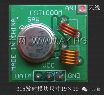
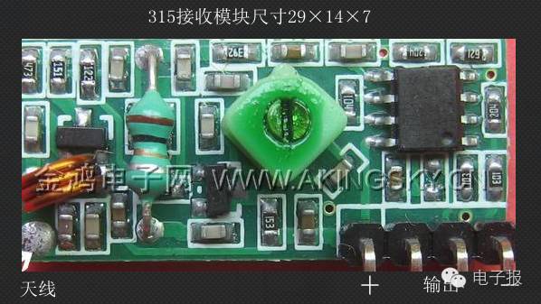
Image 2
One of the challenges in amateur production is the casing. I found a compact shell from a portable charger with dimensions of 33mm× 61mm× 20mm, which can be used to make a handheld transmitter casing. The details are as follows:
1. The transmitter casing must accommodate a φ 4.2mm× 55mm long small pull rod antenna (a 300mm drag line can also be used), a 315 transmitter head, along with an encoding control integrated block VD5026, a 100K encoding oscillation resistor, and a pull-up resistor. A micro switch that serves both as a power source and transmitter is also necessary, and it is advisable to add a power indicator. The remaining space will be for the power supply; due to limited space, I used two CR1632 button batteries connected in series to provide 6V voltage, which are mounted on the printed circuit board. The circuit composition is shown in Figure 1.
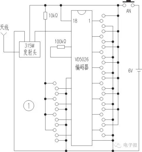
Figure 1
In the figure, the 315M module is a controlled high-frequency oscillator with a 315M surface acoustic wave filter, controlled by VD5026. The oscillation resistor for VD5026 is typically 100K. If this resistor needs to be changed, it must ensure that the oscillation frequencies of VD5026 and VD5027 are consistent, meaning both resistors must be the same; otherwise, the encoding and decoding will not recognize each other. This circuit is only used for remote control of the camera shutter. To simplify the wiring process, all address codes for pins 1-8 are left floating, which reduces the number of printed circuit connections and solder points. If confidentiality is required, pins 1-8 can be connected to high or low levels or left floating as desired. Since there is only one controlled state, the data code for pins 10-13 only takes one pin as high level. In this example, pin 13 is pulled high, while the others are connected to low levels. After assembly, I used a multimeter set to 10mA to measure the current across the switch (the switch is in the off state, indicating it is in the circuit). The current was about 5mA, which is normal. If there is no current, check whether pins 14 and 15 of VD5026 are oscillating and if there is 2V voltage present.
2. The receiver casing is made from a discarded 7.2V1360mA camera battery shell (dimensions 43mm× 29mm× 27mm), removing the internal waste battery for reuse. A piece of universal printed circuit board measuring 42mm× 28mm is cut, and the receiving module is installed upright at the edge. Two CR1632 batteries are also installed upright, while the decoding chip VD5027 is mounted flat. A relay with a pull-in voltage of 5V is then tested for installation. The 315M receiving module is actually a super-regenerative detector receiver, which is then processed by an LM358 dual operational amplifier to shape the output. The DATA output on the board is sent to pin 14 of the decoding chip VD5027, and the decoded output signal drives a transistor to activate the relay. Here, like the encoding chip, pins 1-8 must remain floating; if they change, both encoding and decoding must change accordingly; otherwise, they will not recognize each other. When pressing the transmitter, I found it difficult for the relay to engage. Testing pins 13 and 17 of VD5027 showed high levels, which is normal, but measuring the power supply voltage dropped to about 3.5V, preventing the relay from engaging properly. This was due to the high internal resistance of the CR1632 battery, which could not meet the load requirements. I had to switch to a 23A-12V battery, using the high voltage to compensate for the voltage drop caused by the internal resistance. Fortunately, the casing could still accommodate this battery, so I adjusted the layout of the printed circuit board to fit inside the casing. Considering the short working time of the relay and the voltage drop of the battery, I still used a 5V relay. After increasing the voltage, I added a 78L05 voltage regulator circuit before 5027. After these modifications, the relay operated reliably during testing. The entire circuit is shown in Figure 2.
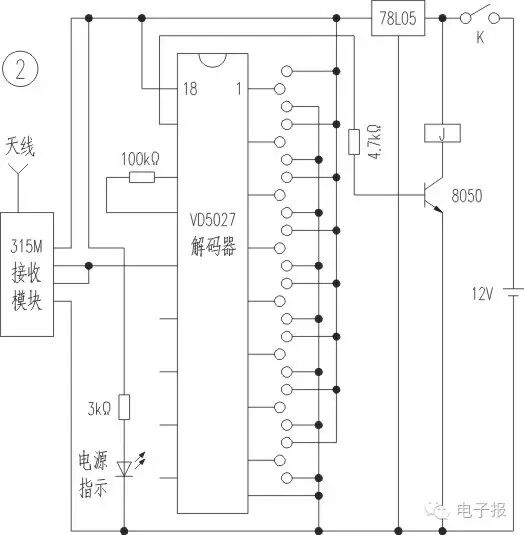
Figure 2
3. After the initial assembly was normal, the next step was to modify the relay. Since the condition for opening the shutter is that the yellow, white, and red wires must all be conductive, and the relay has one normally closed and one normally open contact, it does not meet the conditions. The modification method is to cut around 1.5mm from the edge of the relay lead-out wire (using a knife or hot knife cutting method) to remove the upper cover, cutting the horizontal beam of the normally closed contact. Care must be taken not to damage the lower beam of the normally open contact or the lead wire of the normally open contact. A piece of 0.1mm× 1.5mm× 20mm copper foil is soldered under the lead wire of the normally open contact, then bent to touch the side of the moving contact. The excess copper foil is trimmed and shaped, and using an ohmmeter, I tested for continuity. When I gently pressed the moving contact, it could conduct, and continuing to press would also engage the original normally open contact. It is important that the modified normally open contact engages first and that the resistance caused by the moving contact is minimized. This modification is successful. The relay is then placed on its side on the back of VD5027 and glued with 502 glue, taking care not to use too much glue to avoid liquid flowing onto the pins of VD5027, and the leads are connected properly. The completed remote shutter controller is shown in Photo 3.
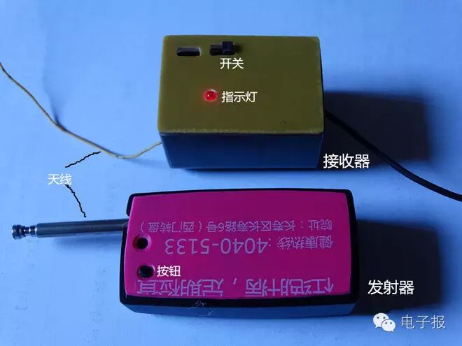
4. Remove the handheld button from the original shutter release cable, keeping the lead wires. Connect the yellow wire from the three leads to the moving contact lead of the receiver, the white wire to the modified normally open contact (originally the normally closed static contact), and the red wire to the original normally open contact to enable linkage testing. Insert the receiver switch lead into the camera, and turn on the camera’s receiver power switch. The camera displays the subject, and the receiver indicator light is on. At this point, holding the transmitter, press the transmit button and observe the camera display showing a record and the shutter sound. Next, continue to perform distance debugging; pulling out the soft drag line of the receiver and the transmitter antenna, pressing the transmitter button, the normal remote control distance can reach 20M. This controller has been used in practice with good results.
It is important to note that the shutter release socket for the Sony DXC-HX300 camera and the common smartphone data cable socket look very similar, but their internal distributions are different, and the internal shapes are also different, making them non-interchangeable. To use a smartphone data cable as a substitute, internal modifications would be necessary, which seems quite challenging. Some cameras have stereo shutter release sockets, such as Canon 600D and 700D; for these cameras, adding a shutter remote control does not require damaging the supplied shutter cable. Instead, a stereo headphone plug can be used to connect, identifying the corresponding wiring relationship for connection.
National Unified Publication Number: CN51-0091 Postal Subscription Code: 61-75
Single issue electronic version subscription is also available (1.5 yuan/issue, 78 yuan/year for 52 issues, PDF format)
Address: (610041) Room 2-1505, Building 7, Tianfu New Valley, 399 West Section, Fucheng Avenue, Chengdu
Website: http://www.netdzb.com
Submission Email: [email protected] Distribution Department, Service Department: 028-65113930 Advertising Department: 028-65113931 Editorial Department: 028-65113932