Principles of Pull-Up Resistor Application1. When a TTL circuit drives a CMOS circuit, if the high level output from the TTL circuit is lower than the minimum high level of the CMOS circuit (generally 3.5V), a pull-up resistor is needed at the TTL output to increase the high level output value. ……………………….2. An OC gate circuit “must have a pull-up resistor to function properly”.3. To increase the driving capability of output pins, pull-up resistors are often used on microcontroller pins.4. On CMOS chips, to prevent damage from static electricity, unused pins cannot be left floating; they are generally connected to a pull-up resistor to lower input impedance and provide a discharge path.5. Adding pull-up resistors to chip pins increases output levels, thereby enhancing the noise tolerance of input signals and improving anti-interference capability.6. It enhances the bus’s resistance to electromagnetic interference. Floating pins are more susceptible to external electromagnetic interference.7. In long line transmissions, impedance mismatches can easily cause reflected wave interference; adding pull-up resistors helps with impedance matching, effectively suppressing reflected wave interference.8. In digital circuits, unused input pins must be connected to a fixed level, either through a 1k resistor to a high level or to ground.Principles for Selecting Pull-Up Resistor Values1. From the perspective of power consumption and the chip’s sinking current capability, the resistor should be sufficiently large; a larger resistor results in smaller current.2. To ensure sufficient driving current, the resistor should be sufficiently small; a smaller resistor results in larger current.3. For high-speed circuits, excessively large pull-up resistors may cause the edges to become sluggish. Considering the above three points, it is typically selected between 1k and 10k. The same reasoning applies to pull-down resistors.The selection of pull-up and pull-down resistors should be “based on the characteristics of the switching transistor and the input characteristics of the subsequent circuit, mainly considering the following factors”:1. The balance between driving capability and power consumption. Taking pull-up resistors as an example, generally speaking, the smaller the pull-up resistor, the stronger the driving capability, but the greater the power consumption; the design should pay attention to the balance between the two.2. The driving requirements of the subsequent circuit. Similarly, taking pull-up resistors as an example, when the output is high, the switching transistor is off, and the pull-up resistor should be appropriately selected to provide sufficient current to the subsequent circuit.3. The setting of high and low levels. Different circuits have different threshold levels for high and low levels, and the resistor should be appropriately set to ensure the correct output level. Taking pull-up resistors as an example, when the output is low, the switching transistor is on, and the voltage divider value of the pull-up resistor and the on-resistance of the switching transistor should ensure it is below the zero-level threshold.4. Frequency characteristics. Taking pull-up resistors as an example, the capacitance between the pull-up resistor and the switching transistor’s source and the input capacitance of the subsequent circuit will form an “RC delay”; the larger the resistor, the greater the delay. The setting of pull-up resistors should consider the circuit’s requirements in this regard.The principles for setting pull-down resistors are the same as those for pull-up resistors.When the OC gate outputs a high level, it is in a high-impedance state, and the pull-up current must be provided by the pull-up resistor. Assuming the input current for each port does not exceed 100uA, and the output driving current is about 500uA, the standard operating voltage is 5V, with input high and low level thresholds of 0.8V (below this value is low level) and 2V (high level threshold value).When selecting a pull-up resistor: 500uA x 8.4K = 4.2, thus selecting a value greater than 8.4K ensures the output can pull down to below 0.8V; this is the minimum resistance value, and any smaller will not pull down sufficiently. If the output driving current is larger, the resistance value can be reduced, ensuring it can pull down below 0.8V. When the output is high, ignoring the leakage current of the transistor, both input ports require 200uA, 200uA x 15K = 3V, thus the voltage drop across the pull-up resistor is 3V, allowing the output to reach 2V; this resistance value is the maximum resistance value, and any larger will not pull down to 2V. A value of 10K is acceptable. 【Maximum voltage drop / Maximum current, Minimum voltage drop / Minimum current】For CMOS gates, refer to the 74HC series; the leakage current of the transistors cannot be ignored, and the actual current at the IO port varies at different levels. The above is merely a principle, summarized as: “When outputting a high level, ensure the subsequent input ports are adequately supplied; when outputting a low level, do not overload the output port” (otherwise, excess current supplied to the cascaded input ports may exceed the low-level threshold, making it unreliable).Additionally, the following points should be noted:A. Check what device the output port is driving; if that device requires a high voltage, and the output port’s voltage is insufficient, a pull-up resistor is needed.B. If there is a pull-up resistor, its port defaults to a high level; to control it, a low level must be used, such as controlling the collector of a transistor in a tri-state gate circuit or the anode of a diode to pull the pull-up resistor’s current down to a low level. Conversely,C. Especially in interface circuits, to achieve a definite level, this method is generally adopted to ensure the correct circuit state and avoid accidents. For example, in motor control, the upper and lower arms of an inverter bridge cannot be directly connected; if they are driven by the same microcontroller, an initial state must be set to prevent direct connection!Driving should preferably use sinking current.When selecting resistors, choose the one that is closest to the calculated standard value!Reasons for Pull-Up Resistors on P01. The P0 port has no internal pull-up resistor.2. When the P0 is in I/O mode, the upper FET is turned off, causing the output pin to float; thus, P0 acts as an open-drain output when used for output lines.3. Due to the lack of an internal pull-up resistor and the upper FET being turned off, when P0 outputs a 1, it cannot raise the port level.P0 is a bidirectional port, while P1, P2, and P3 are quasi-bidirectional ports. Quasi-bidirectional ports require a “preparation” step when reading external data; why is this necessary?When the microcontroller reads the quasi-bidirectional port, it must first set the port latch to 1, to turn off the FET and prevent the port from being held at a low level due to the internal FET being on.Generally, pull-up and pull-down resistors are selected at 10k!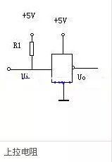

Disclaimer:This article is original by the author, and the content reflects the author’s personal views. The Electronics Enthusiast Network reproduces it merely to convey a different perspective and does not represent the Electronics Enthusiast Network’s endorsement or support of this view. If there are any objections, please contact the Electronics Enthusiast Network.Read More Exciting Articles
-
In-depth | Uncovering the essentials, delving into potential, AI facial recognition enters an accelerated implementation phase!
-
Apple’s 5G phone delayed, Huawei P40 is appealing; who can seize the first wave of growth in 5G phones?
-
Online packed! The 2020 BLDC Brushless DC Motor Control Technology Seminar was successfully held!
-
The Crazy Ventilator: A rollercoaster game of explosive orders and stockpiling
-
The explosive rise of mask machines! Domestic and export demand booming, will it usher in another surge?