Resistive sensors, along with their corresponding measuring circuits, are essential tools for automatic weighing, process detection, and achieving automation in production processes across various sectors such as metallurgy, power, transportation, petrochemicals, commerce, biomedicine, and national defense. They are used in measuring force, pressure, weight, displacement, acceleration, torque, and more.
Resistive Sensors

Resistive sensors convert the changes in the measured variable into changes in the resistance parameters of the sensitive element through specific methods, and then output voltage or current signals through circuits, thus achieving the measurement of non-electric quantities.
They can be used to detect various mechanical and thermal quantities, such as force, pressure, displacement, strain, speed, acceleration, temperature, and humidity. They have a simple structure, stable performance, and low cost, making them widely used in many industries.
Due to the variety of materials that constitute resistors and the numerous physical reasons that cause resistance changes, various resistive sensing elements and resistive sensors composed of these elements have been developed.
Advantages and Disadvantages of Resistive Sensors
1. Advantages of Resistive Sensors
1) They exhibit significant non-linearity and weak output signals, but certain compensation measures can be taken. Therefore, they are widely used in automatic testing and control technologies.
2) The resistance strain gauges in resistive strain sensors demonstrate a metal strain effect, meaning they produce mechanical deformation under external forces, causing the resistance value to change accordingly.
2. Disadvantages of Resistive Sensors
1) They exhibit significant non-linearity for large strains, but the output signal is weak.
2) The materials and device performance constituting the sensor can change over time and with environmental variations. Therefore, they are not suitable for long-term monitoring due to significant drift over time and temperature, which may prevent obtaining real and effective data after prolonged measurement.
3) They are easily affected by electric fields, magnetic fields, vibrations, radiation, air pressure, sound pressure, airflow, and more.
Resistance Strain Sensors
Resistance strain sensors are made based on the principle of the resistance strain effect, converting the deformation of the measured object into changes in resistance. They are mainly used for detecting mechanical quantities such as force and pressure, with the most widely used form being resistance strain gauges.
Resistance Strain Effect: Conductors or semiconductor materials undergo mechanical deformation under external forces, which also causes changes in their resistance. This phenomenon is known as the resistance strain effect.
The working principle of metal resistance strain gauges is based on the resistance strain effect.
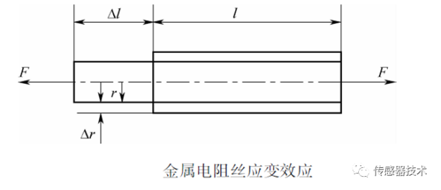
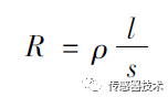
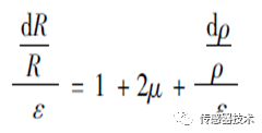
The resistance value of metal conductors can be expressed as:
1. Structure of Resistance Strain Gauges
Resistance strain gauges, also known as resistance strain meters, have various structural forms, but their main components are generally the same, consisting of a substrate, a sensitive grid, and a cover layer.
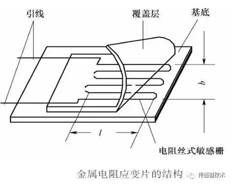
1) Sensitive Grid – The sensitive component that converts strain into resistance. It is usually made of metal wire with a diameter of 0.015 to 0.05 mm wound into a grid shape or etched from metal foil.
2) Substrate – To maintain the shape, size, and position of the sensitive grid, it is usually bonded to a paper or resin substrate using an adhesive. The substrate must be thin, generally 0.02 to 0.04 mm.
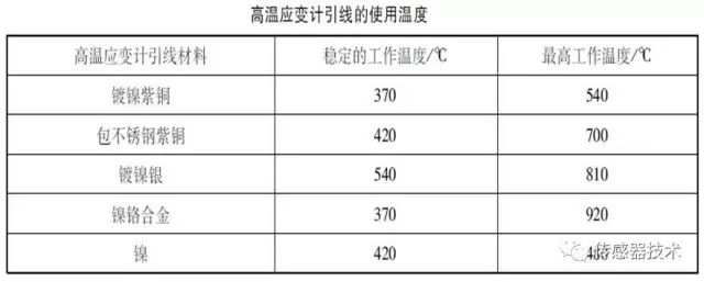
3) Leads – Serve as the transition connection and guidance between the sensitive grid and the measuring circuit. They are typically low-resistance tin-plated copper wires with a diameter of about 0.1 to 0.15 mm, soldered to the ends of the sensitive grid.
4) Cover Layer – A protective layer made of paper or resin covering the sensitive grid, serving to protect against moisture, corrosion, and damage.
5) Adhesive – Used to bond the cover layer and sensitive grid to the substrate during the manufacturing of the strain gauge. When using the strain gauge, it adheres the strain gauge substrate to the surface of the measured part, also playing a role in transmitting strain.
2. Requirements for Resistance Strain Gauges:
1) High strain sensitivity coefficient and wide linear range;
2) High resistivity, meaning a larger resistance value in wires of the same length and cross-sectional area;
3) Good resistance stability, small temperature coefficient, with resistance value changing little with environmental temperature;
4) Easy to solder, with small contact potential for lead materials;
5) High oxidation resistance, corrosion resistance, fatigue resistance, high mechanical strength, and excellent machinability.
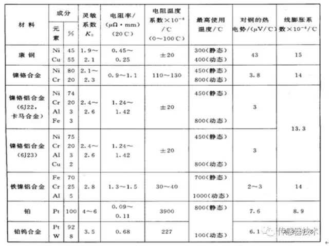
Properties of commonly used metal resistance wire materials:
3. Classification of Resistance Strain Gauges
Resistance strain gauges can be classified based on their manufacturing methods, working temperatures, and applications.
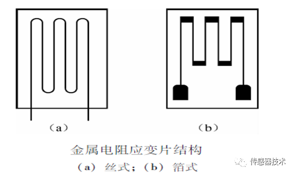
Based on the materials used for the strain gauges, they can be divided into metal resistance strain gauges and semiconductor strain gauges.
Metal Resistance Strain Gauges
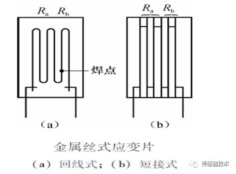
Wire-type strain gauges consist of substrate materials, metal strain wires or strain foils, insulating protective sheets, and lead wires.
Wire-type strain gauges come in two forms: backline type and short-circuit type. The backline type is the most common, easy to manufacture, stable in performance, low in cost, easy to adhere, but has a larger transverse effect. The sensitive grid of wire-type metal resistance strain gauges is formed by parallel arrangement of resistance wires with diameters of 0.01 to 0.05 mm. The resistance value of the strain gauge is typically in the range of tens of ohms to several tens of kilohms.
Metal Foil Resistance Strain Gauges
The sensitive grid is made using processes such as photolithography and etching. Alloys are first rolled into foils with thicknesses of 0.002 mm to 0.01 mm, and after heat treatment, a layer of resin glue with a thickness of 0.03 mm to 0.05 mm is coated on one side, which is then polymerized and cured to form the substrate. The sensitive grid is created on the other side using photographic methods, photolithography, and etching, followed by soldering leads and coating with the same resin glue as the substrate for protection.
Main Features of Foil Strain Gauges:
1) In terms of process, it ensures accurate dimensions of the sensitive grid and uniform lines. When mass-produced, it has good consistency and low dispersion of resistance values.
2) The cross-sectional area of the sensitive grid of foil strain gauges is rectangular, with a large surface area to cross-sectional area ratio, good heat dissipation, and allows larger currents to pass through, resulting in higher sensitivity coefficients.
3) Foil strain gauges are thinner than wire strain gauges, typically 0.003 mm to 0.01 mm thick. Due to their thinness, they have better flexibility, allowing them to be shaped into any desired form (i.e., strain flowers) and micro small base lengths (e.g., base length of 0.1 mm), facilitating deformation transmission.
4) Due to the special process of foil strain gauges, they are suitable for mass production and have high production efficiency.
Metal Thin Film Strain Gauges
A thin film generally refers to a film with a thickness not exceeding 0.1 μm. Metal thin film strain gauges are made using methods such as vacuum deposition, deposition, or sputtering to form a thin layer of metal resistance material on a very thin insulating substrate material to create the sensitive grid, followed by adding a protective layer.
Metal thin film strain gauges can be made from high-temperature materials that can operate under high-temperature conditions. For example, platinum or chromium can be deposited on sapphire sheets or molybdenum strips coated with ceramic insulation layers, with working temperature ranges from 600°C to 800°C.
If classified by working temperature, resistance strain gauges can be divided into low temperature (below -30°C), normal temperature (-30°C to 60°C), medium temperature (60°C to 300°C), and high temperature (above 300°C).
4. Measuring Circuit of Resistance Strain Sensors
The measuring circuit of resistance strain sensors can be classified into direct current measuring circuits and alternating current measuring circuits based on the power supply.
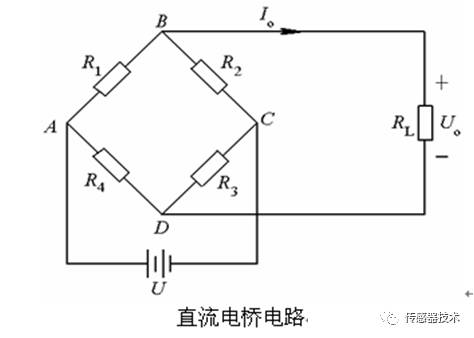
1) DC Bridge Circuit
The DC bridge circuit consists of four bridge arms connected in a loop, each with a resistor, R1, R2, R3, and R4, which can all or partially be strain gauges.
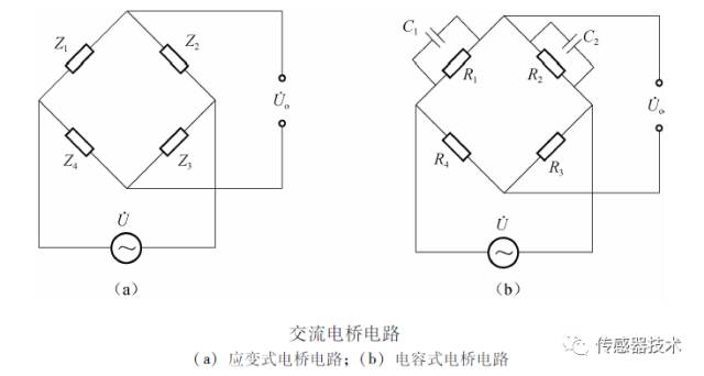
2) AC Bridge Circuit
Since the output voltage of strain bridges is very small, amplifiers are generally required. However, DC amplifiers are prone to zero drift, so strain bridges mostly use AC bridges.
3) Balancing the Bridge
Before the strain gauge operates, the bridge must be balanced. For DC bridges, series or parallel potentiometer methods can be used. Common bridge balancing circuits are shown in the figure.
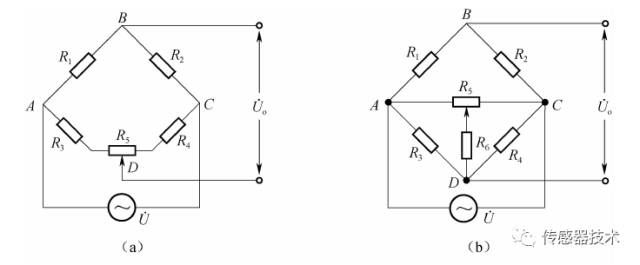
(a) Series Resistance Balancing Method (b) Parallel Resistance Balancing Method
For AC bridges, resistance-capacitance balancing methods are generally used, as shown in the figure.
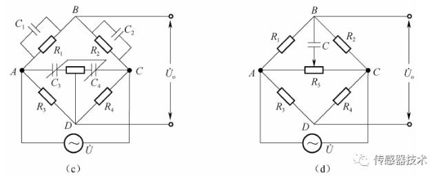
(c) Differential Capacitor Balancing Method (d) Resistance-Capacitance Balancing Method
5. Adhesion of Resistance Strain Sensors
Strain gauges are adhered to the measured object using adhesives, which must accurately and quickly transmit the strain from the measured object to the sensitive grid. When choosing adhesives, the properties of the strain gauge material and the measured object must be considered, requiring strong adhesion, reliable mechanical properties after bonding, and sufficient shear elastic modulus, good electrical insulation, low creep and hysteresis, moisture resistance, oil resistance, aging resistance, and fatigue resistance during dynamic stress measurements.
The steps for adhering strain gauges can generally be divided into:
(1) Inspection and selection of strain gauges
(2) Surface treatment of the test piece
(3) Bottom layer treatment
(4) Attachment
(5) Curing
(6) Adhesion quality inspection
(7) Soldering leads and connecting the bridge
Selection of strain gauges:
(1) Type selection – purpose, requirements, object, environment
(2) Material considerations – operating temperature, time, maximum strain, and accuracy.
(3) Resistance value selection – based on the measuring circuit and instrument for nominal resistance
(4) Size considerations – surface of the test piece, stress distribution, adhesion area
(5) Other considerations – special uses, harsh environments, high precision
6. Applications of Resistance Strain Sensors
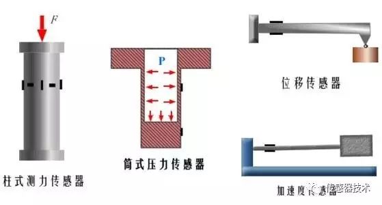
Resistance strain gauges have two main applications: first, as sensitive elements, they can be directly used for measuring the strain of tested objects; second, as conversion elements, they can form sensors through elastic elements, allowing for indirect measurement of other physical quantities that can be converted into the strain of elastic elements.
Characteristics of strain gauge sensors:
1) Wide range of applications and measurements;
2) High resolution and sensitivity, with relatively high accuracy;
3) Lightweight structure, minimal impact on the test piece, strong environmental adaptability, and good frequency response;
4) Commercially available, convenient selection, and easy to implement long-distance, automated measurements.
1) Force Sensors:
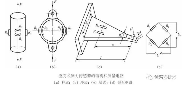
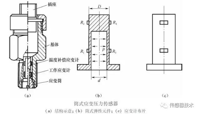
2) Pressure Sensors:
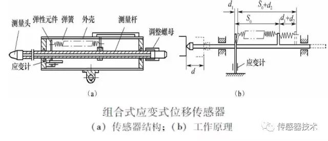
3) Strain Displacement Sensors:
Strain displacement sensors convert the measured displacement into the deformation and strain of elastic elements, and then output an electrical quantity proportional to the measured displacement through strain gauges and strain bridges.
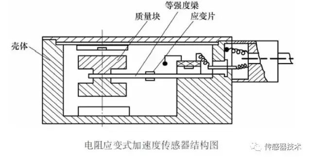
4) Strain Acceleration Sensors:
By utilizing the interaction between a mass block and elastic elements, the measured acceleration can be converted into elastic strain, thus forming strain acceleration sensors.
Piezo-resistive Sensors
Some solid materials experience changes in their resistivity ρ when subjected to external forces in a certain axial direction, in addition to deformation. This phenomenon, where the resistivity of materials changes due to stress, is known as the piezo-resistive effect. The piezo-resistive effect is particularly strong in semiconductor materials. Sensors made using the piezo-resistive effect are called piezo-resistive sensors.
Piezo-resistive sensors have a high sensitivity coefficient, high resolution, good frequency response, and small size. They are mainly used to measure parameters such as pressure, acceleration, and load.
1. Classification of Piezo-resistive Sensors
Piezo-resistive sensors are pure resistive elements made using the piezo-resistive effect of semiconductor materials. They mainly come in three types: bulk, thin film, and diffusion.
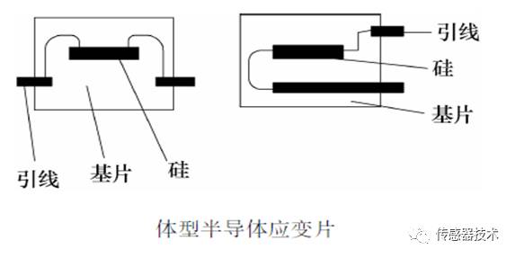
1) Bulk Piezo-resistive Sensors
These are made using semiconductor material resistors that are bonded as strain gauges (semiconductor strain gauges), based on the piezo-resistive effect of semiconductor materials. They consist of small strips of silicon or germanium crystals cut in a specific direction and bonded onto a substrate.
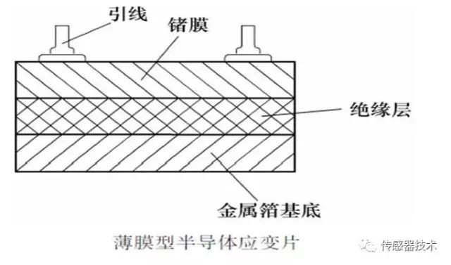
2) Thin Film Piezo-resistive Sensors
Thin film piezo-resistive sensors are made by depositing semiconductor materials onto test pieces with insulation layers using vacuum deposition technology.
3) Diffusion Piezo-resistive Sensors
Diffusion piezo-resistive sensors are made using integrated circuit processes on semiconductor material substrates to create diffusion resistors. P-type impurities are diffused into N-type silicon single crystal substrates, forming a very thin P-type conductive layer, with leads attached through ultrasonic and thermal pressure welding to create diffusion semiconductor strain gauges.
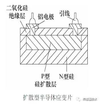
This is a widely used type of semiconductor strain gauge. The substrate of diffusion piezo-resistive sensors is single crystal silicon.
2. Working Principle of Piezo-resistive Sensors
1) Working Principle
Piezo-resistive sensors are made from semiconductor materials, and their working principle is based on the piezo-resistive effect of semiconductor materials. When the semiconductor strain gauge is subjected to axial forces, its resistivity changes. The relative change in resistance is:
When measuring strain or stress using strain gauges, the object under external force undergoes slight mechanical deformation, and the strain gauge experiences the same change, resulting in a corresponding change in the resistance value of the strain gauge. Compared to metal strain gauges, semiconductor strain gauges have the most prominent advantage of being smaller in size and having higher sensitivity.
2) Temperature Errors and Compensation
Due to the high sensitivity of semiconductor materials to temperature, the resistance value and sensitivity coefficient of piezo-resistive sensors change with temperature variations, leading to temperature errors known as zero drift and sensitivity temperature drift. Piezo-resistive sensors generally have four diffused resistors on the semiconductor substrate; when the resistance values of the four diffused resistors are equal or differ little, and their temperature coefficients are similar, both zero drift and sensitivity temperature drift will be minimal, though this is difficult to achieve in practice. Due to significant temperature errors, piezo-resistive sensors generally require temperature compensation.
3. Applications of Piezo-resistive Sensors
Using the piezo-resistive effect of semiconductors, various types of piezo-resistive sensors can be designed. Piezo-resistive sensors are small in size, have a relatively simple structure, high sensitivity, and can measure micro pressures of several tens of micro pascals, with good dynamic response and long-term stability, low hysteresis and creep, and high frequency response. Therefore, they are widely used in measuring pressure, differential pressure, liquid level, acceleration, and flow.
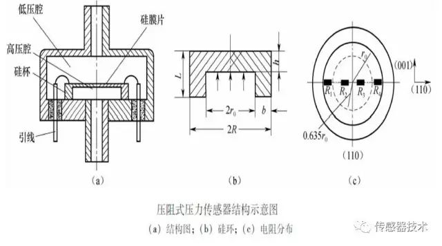
1) Pressure Measurement
The silicon piezo-resistive pressure sensor consists of a casing, a silicon diaphragm (silicon cup), and leads.
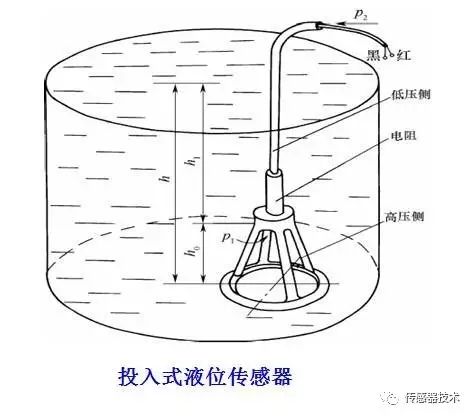
2) Liquid Level Measurement
This works on the principle that the height of the liquid surface is proportional to the liquid pressure. Submersible liquid level sensors are easy to install and can adapt to liquid level measurements in depths ranging from several meters to dozens of meters, even in water or other liquids mixed with a lot of impurities.
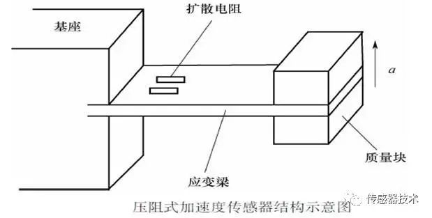
3) Acceleration Measurement
Its cantilever beam is made directly from single crystal silicon, with four resistors of equal value diffused at the root of the cantilever beam, forming a differential full bridge. A mass block is attached to the free end of the cantilever beam; when the sensor experiences acceleration, the inertial effect of the mass block causes the cantilever beam to deform and produce stress, which changes the resistance values of the diffused resistors. The output signal from the bridge can be used to obtain the magnitude of the acceleration.
With the development of integration technology, various mixed integrated and single-chip integrated sensors that are multi-functional and intelligent are widely used. Integrated sensors include piezo-resistive and capacitive types, with piezo-resistive integrated sensors developing rapidly and having wide applications.
– END –
Source: Sensor Technology

Previous Articles
Notice for the 2020 Annual Meeting of the China Aviation Industry Technology Equipment Engineering Association Call for Papers
Notice for the 17th China Aviation Measurement and Control Technology Annual Meeting Call for Papers
Notice for the “Artificial Intelligence and Testing Assurance” Column Call for Papers in Measurement and Control Technology
Open Reading Download | Table of Contents and Full Text of Measurement and Control Technology 2020 Issue 6