
Recently, I came across an open-source project called meshtastic. It primarily builds a decentralized network using LoRa spread spectrum communication. In China, it is likely more suitable for mountainous areas and rescue communication scenarios, as we can make phone calls as long as we are not deep in the mountains.
This project mainly uses the ESP32 as the main control MCU and the LoRa communication module, due to the good ecosystem of the ESP32. Additionally, the ESP32 has Bluetooth and WiFi capabilities, which allows us to easily communicate with the device via a mobile app, bridging the user interface of the decentralized network. On the other hand, based on the WiFi link, we can connect multiple sub-networks over long distances through MQTT services, forming a large network.
When I started designing the hardware for this open-source project, I first encountered the issue of program downloading. The meshtastic project provides a web-based page that can directly call the serial port to download to our target board.
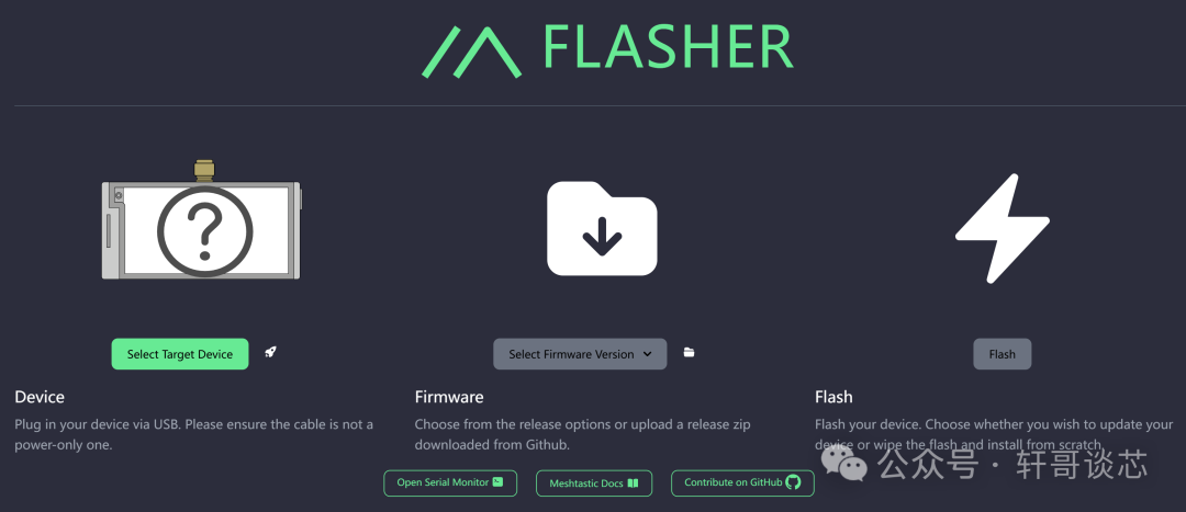
This is indeed an interesting matter; calling USB devices from the web requires using the Chrome browser. Additionally, for USB to serial conversion, we need to use the DTR and RTS signal pins. These two pins generate a special timing to trigger the ESP32 to enter ISP mode.
The DTR (Data Terminal Ready) and RTS (Request to Send) in serial tools are two pins in the RS-232C interface standard, which have the following meanings:
-
DTR (Data Terminal Ready): When this pin is high, it indicates that the data terminal device (such as a computer) is ready for data transmission. Typically, the DTR signal is sent from the data terminal device to the serial device (such as a modem) to indicate that the serial device should start data transmission.
-
RTS (Request to Send): When this pin is high, it indicates that the data terminal device (such as a computer) requests the serial device (such as a modem) to start data transmission. Typically, the RTS signal is sent from the data terminal device to the serial device to request the initiation of the data transmission process.
In summary, DTR and RTS are key signals used to control data transmission in serial communication, representing the readiness state of the data terminal device and the transmission request, respectively. Through these two signals, we can achieve coordinated operation between the data terminal device and the serial device to complete data transmission tasks.
In practical applications, DTR and RTS are often used to implement full-duplex communication, meaning that data can be sent and received simultaneously. When both DTR and RTS are high, it indicates that the data terminal device is ready to send data and requests the serial device to start receiving data. At this point, the serial device will initiate the data reception process upon receiving the RTS signal.
Simply put, the computer, which is our host program, can control the output of these two pins to high and low levels.
So, what levels and timing does the ESP32 need to enter ISP mode?
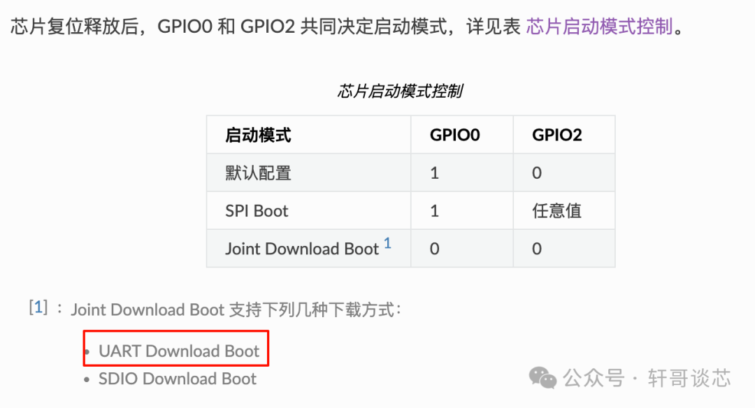
From the official manual, we can see that we need to select the UART Download Boot mode, which allows us to directly use uart0 for program downloading. The way to enter this mode is to pull GPIO0 low during the chip startup. The specific timing is also provided in the official specifications, as shown in the following image:
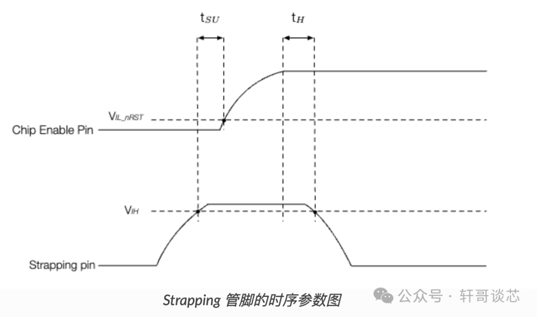
Thus, we can determine what kind of timing is needed on the chip’s RST pin and GPIO0.
Here, I mainly studied the following circuit, which is compatible with both manual and automatic download modes, making it compatible with various download software.
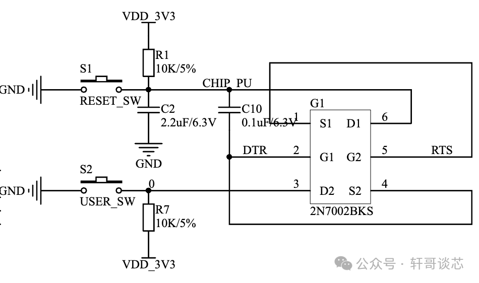
First, the left side of the circuit diagram is relatively simple, using the combination of two buttons to control the download mode of the ESP32.
Then, the right side of the circuit is configured through the DTR and RTS pins of the USB to serial chip, where CHIP_PU is the EN pin of the ESP32, which is also the RST reset pin, while the 0 at the upper end of R7 is the network of GPIO0. The chip 2N7002BKS is a dual MOSFET packaged chip, and from the pin names, it can be seen that it has two pairs of GDS MOSFETs.
I will simplify it for analysis.
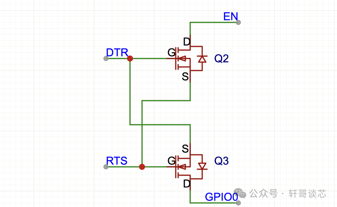
When DTR=0 and RTS=0, both Q2 and Q3 are off, so EN and GPIO0 will follow the manual download logic.
When DTR=0 and RTS=1, Q3 is on, Q2 is off, EN remains in the external state, and GPIO0 is pulled low to 0.
When DTR=1 and RTS=0, Q2 is on, Q3 is off, EN is pulled low to 0, and GPIO0 remains in the external state.
When DTR=1 and RTS=1, both Q2 and Q3 are off, and the state returns to the external holding state.
From the timing diagram, we actually need a segment where EN and GPIO0 are both pulled low, but from the above state transitions, the logic of pulling EN and GPIO0 low simultaneously has not been achieved.
Here we need to look at the circuit design; I simplified it too much and neglected the capacitor hanging on the EN pin.
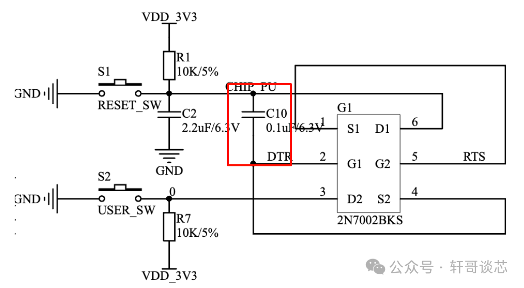
With this capacitor, after powering on, it maintains manual mode, with both GPIO0 and EN pulled high.
We send the serial status, pulling DTR = 1 and RTS = 0. At this point, GPIO0 remains in the external state and is pulled high. EN is pulled low to 0. At this time, C10 has already been charged.
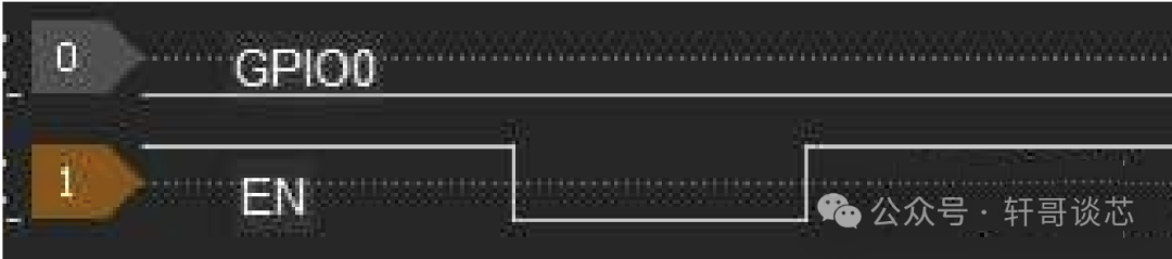
Then, we pull RTS = 1 and DTR = 0. At this point, GPIO0 will be quickly pulled low to 0. However, the EN pin will not immediately go high due to the presence of the capacitor, and DTR being 0. To return to high, a discharge and charge process is needed.
Thus, we obtain a rising edge, and at this point, GPIO0 has already been quickly pulled low to 0.