Abstract: After a failure in my freshman year, I decided to temporarily halt the development of this project and first learn the basics of embedded development. I planned to complete this hexapod robot independently when I had the capability. Fortunately, just as my undergraduate studies were coming to an end, I had acquired enough knowledge to finish the robot project that had troubled me for a long time. Thus, I spent a few weeks completing this hexapod robot, fulfilling a personal wish.
1. Introduction
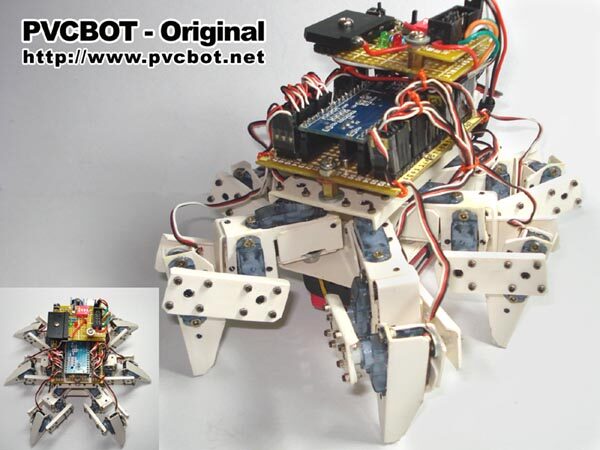
This hexapod robot is a personal project I undertook in my senior year, marking the last individual project of my undergraduate career. The motivation for creating a hexapod robot dates back to after my college entrance examination: I wanted to do something interesting. One day, I discovered a website called PVCBOT, which documented many tutorials on how to make simple robots using PVC materials. One particular robot, the PVC Hexapod Insect, completely amazed me. After reading the tutorial, I resolved to create a similar hexapod robot. I purchased a hexapod robot kit from a senior named Lazy Cat (which should be out of print now) and intended to follow the provided tutorial to complete my robot. However, at that time, I lacked the necessary knowledge in microcontrollers, serial communication, servo PWM, power management, sensors, and servo control boards, especially in mechanical structures. In my freshman year, I even made a joke: I made the limbs of the hexapod robot out of hard cardboard, and after installing the servos and powering it on, I watched helplessly as my “cardboard hexapod” fell apart under the servo’s vibrations…
2. Overview
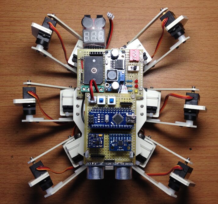
The hexapod bionic robot is a mini multi-legged robot with eighteen degrees of joint freedom. It can achieve basic functions such as infrared remote control and ultrasonic obstacle avoidance. The core hardware of the robot is based on the Arduino Nano, which communicates with a 24-channel servo control board via serial communication to achieve precise control of all servo rotation angles, allowing the robot to move in various gaits. Additionally, the software for this robot project is open-source, and the specific code can be obtained from my GitHub repository.

3. Production
The entire production process of the hexapod robot is mainly divided into mechanical and electronic parts. Since each step in the tutorial is very clear with images, the mechanical part did not take much time and effort. However, the electronic part was entirely designed by me. Although the principles were not very difficult, selecting the placement of the perforated board based on the robot’s mechanical structure and completing the layout and soldering of electronic components was quite labor-intensive. Sometimes, if not handled well, it required rework. Fortunately, I had planned the circuit beforehand, so the production of the circuit part went relatively smoothly.
In the following sections, I will explain some specific steps and details of the robot production process as thoroughly as possible. If you are more interested in the principles and final effects of the robot, you can skip this section and directly read the principles and effects chapters.
3.1 Mechanical
Hexapod Shank
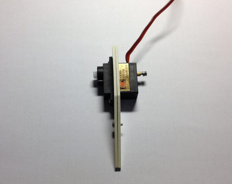
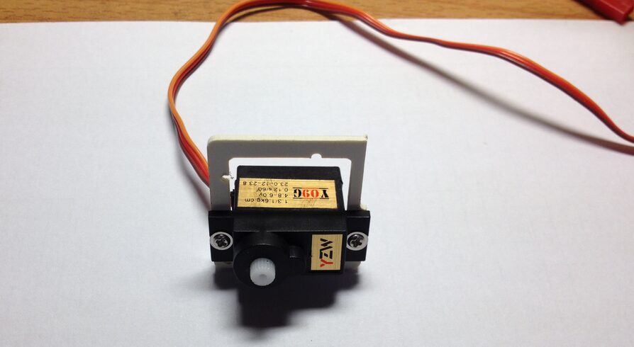
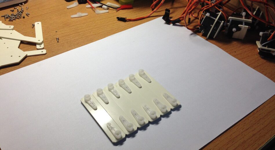
As shown in the figure below, the hexapod’s shank is mainly composed of two PVC limbs stacked together, with a 9G metal gear servo used for the joint. Only two self-tapping screws are needed to securely fix the PVC limbs to the servo, ensuring that the hexapod shank can exert enough force to support the entire body when in contact with the ground.
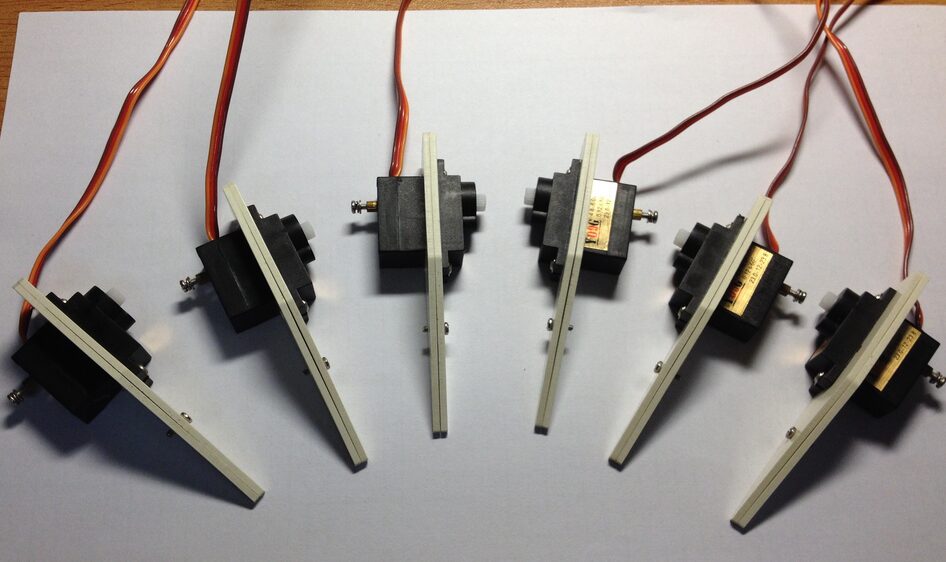
As this is a hexapod robot, five more shanks of the same structure need to be produced. Note: The robot’s body has three shanks on each side, symmetrically arranged, so it is crucial to ensure that the limbs and servos are installed correctly to maintain structural symmetry.
Hexapod Thigh
Joint
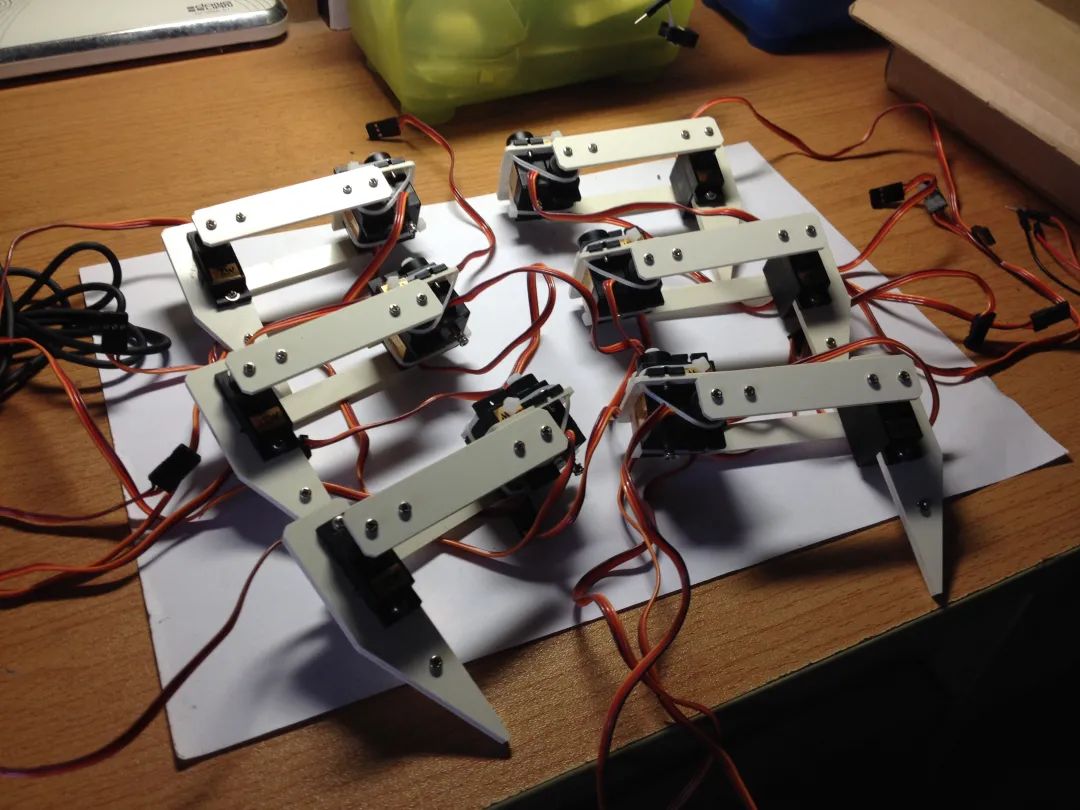
The joint structure of the hexapod’s thigh is slightly more complex than that of the previously introduced shank joints because the thigh joints involve movement in both the vertical and horizontal dimensions of the robot’s body. Therefore, two servos are needed to achieve this. As shown in the figure below, we first use screws to fix one servo in the square joint limb.
Next, we need to repeat the above installation steps to create six similar limb structures. However, during production, it is also important to ensure that the three limb structures on the left and right sides of the robot remain symmetrical.
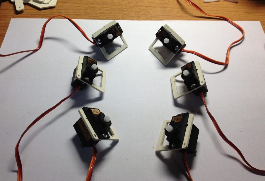
Then, we need to insert six servos into the previously reserved slots in the limbs, ensuring that the two servos in each group are positioned perpendicularly to each other, i.e., the orientation of the servo’s circular rotation axis should be one forward and one upward as shown in the figure below.
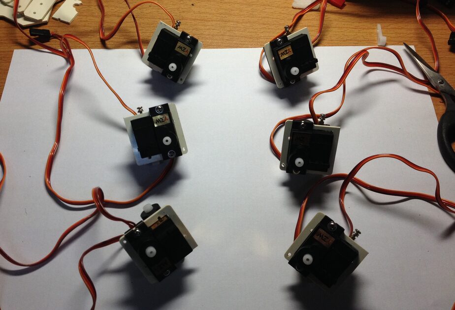
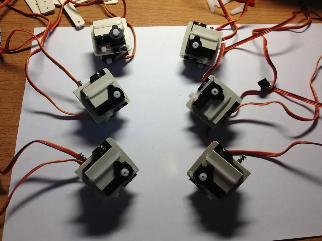
Next, install the fixing plate for the hexapod thigh joint, which is clipped onto the circular rotation axis of the servo shown in the front of the figure below. The fixing plate, as the name suggests, is used for stabilization, primarily to prevent the two servos at the joint from shifting positions due to vibrations from the body.

Finally, use two plastic zip ties to further reinforce each joint group, one passing over the fixing plate to tighten it, and the other passing through a small hole on the side of the joint to secure the structure.
Thigh
The hexapod’s thigh is composed of two rectangular PVC long rods, and it can be clearly seen in the figure below that each rod has matching servo plates installed on both sides, which are mainly used to connect the hexapod’s shank joints and thigh joints.
Hexapod Body
As shown in the figure below, use screws to connect the previously made pairs of shanks and thighs together. Although there is no difficulty in screwing, there are regulations on where to fix the servos: the servo’s rotation axis must return to its original midpoint position (for servos with a rotation range of 0~180°, the midpoint position is 90°) before being connected to the limbs. This is to ensure that all servos have the most suitable range of motion, preventing asymmetrical movement of the body during movement. As for how to return the servo to the midpoint, one method is to use a ready-made servo debugging board, which can adjust the position of the servo by moving the knob; the other is to write an Arduino program to automatically center the servo upon power-up. I used the second method, and it worked quite well.
Next, we need to install all the hexapod’s body onto the top body. Similarly, before installation, ensure that the servos to be connected are already centered. Additionally, the side of the body designated as the robot’s head and the side as the tail must be predetermined to avoid installing the body incorrectly.
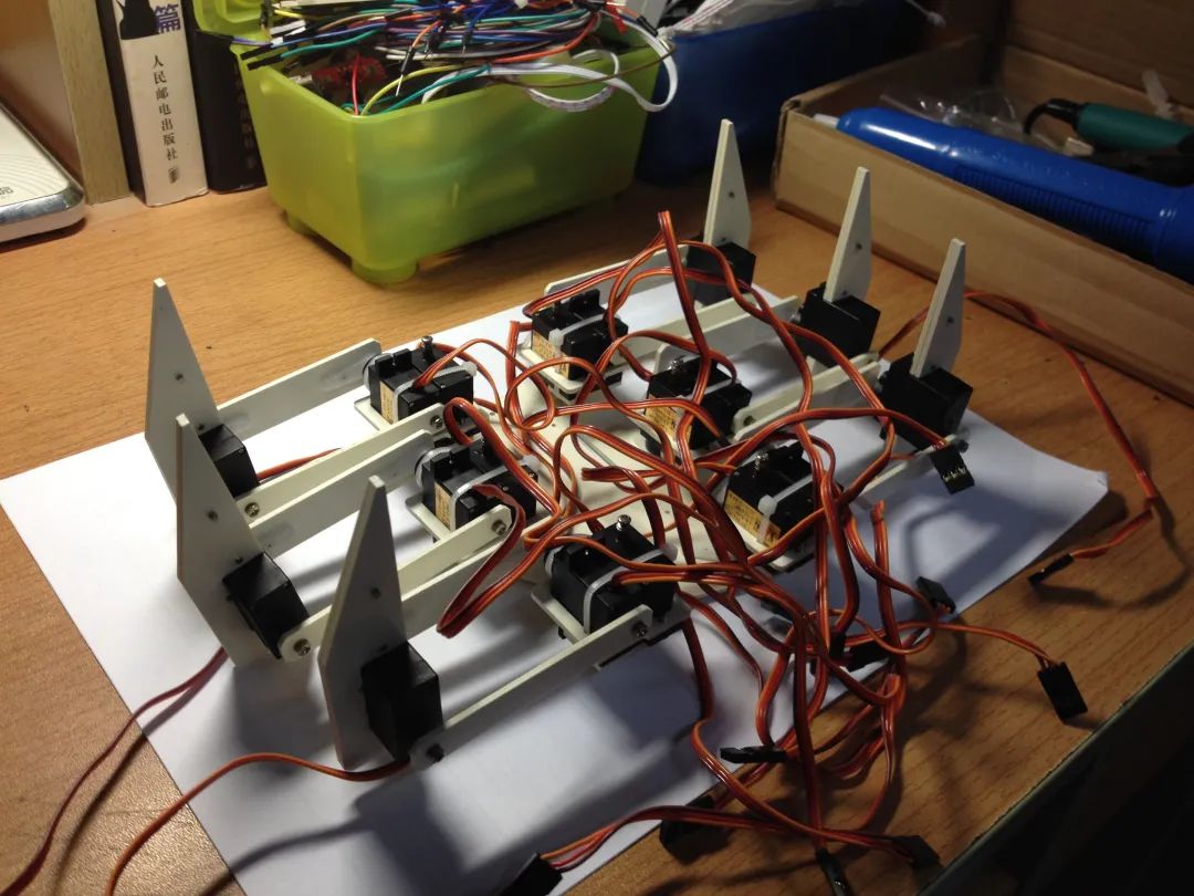
As shown in the figure, we can first find a slightly elevated object to raise the top of the robot, then use zip ties to bundle the three servo wires of each limb together. This not only makes it look more aesthetically pleasing and easier to organize and connect later, but also effectively prevents the servo wires from tangling or being pulled apart during movement. After all, during my time at the university’s robotics lab, I personally experienced the tragedy of motor wires being violently torn during the movement of the robotic arm…
Finally, we just need to secure the lithium battery to the tail of the bottom body with zip ties, then lead out the power line and charging line, and stuff all the bundled servo wires into the body in order, securing the top and bottom bodies together with screws to complete the assembly (I didn’t take photos of this part, so I described it in words).
3.2 Electronics
Power Management
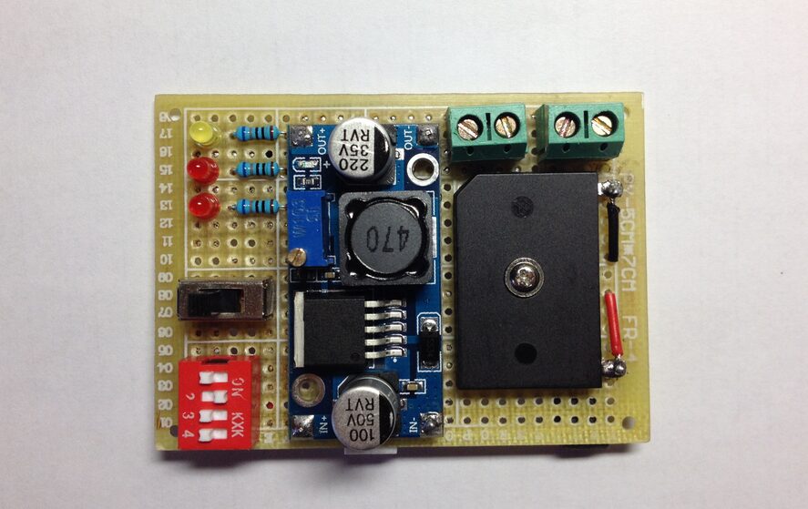
The figure below shows the robot’s power management module. The power management module mainly includes power supplies, buck circuits, and control circuits, and the specific principles can be found in the power management section of the principles below.
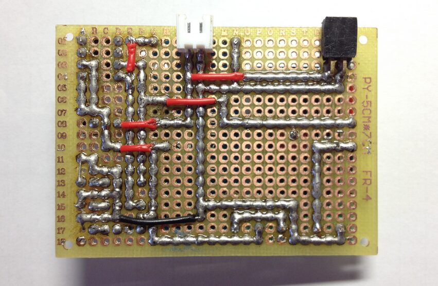
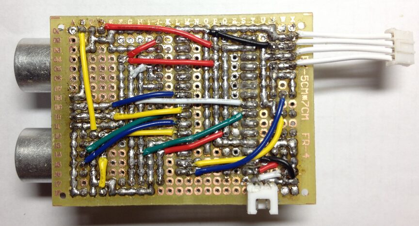
The figure below shows the back of the power management module. To keep the soldered circuit neat and beautiful, I tried to use soldered wire connections for all components, only using traditional flying wires where soldering was not possible. Although the advantages of soldered wire connections are obvious, they also have prominent drawbacks: one is the waste of solder and the other is the risk of short circuits, which can significantly impact the robot. I remember once I carelessly placed the powered power management module on top of the hexapod robot, and to my surprise, the head of the screw fixing the body happened to be stuck between the soldered wire connections of the power supply’s positive and negative terminals, and the result is predictable.
Therefore, before powering on for testing, everyone should use a multimeter to perform short circuit tests on the soldered circuit, ensuring that no excess solder debris remains on the circuit board. Additionally, for circuit boards soldered using the soldered wire connection method, the back should not come into contact with any potential conductive materials. It is advisable to use copper pillars to raise the board or use hot glue to cover the entire back of the board to prevent short circuit issues.
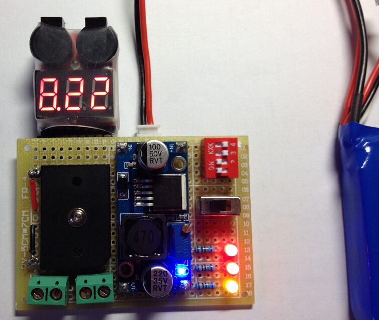
Once it is ensured that there are no potential short circuit issues in the circuit, the power-on test can be performed as shown in the figure below. The test mainly checks whether the power supply voltage drop meets the expected value and whether the logic of the switch is correct.
Control Unit
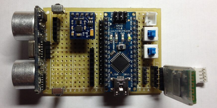
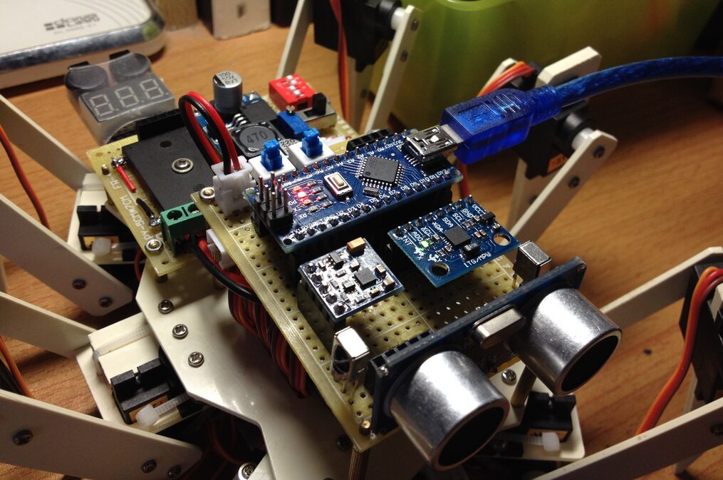
The figure below shows the robot’s control unit module. This control unit module mainly consists of the Arduino Nano control board, HMC58883L electronic compass sensor, MPU6050 inertial measurement sensor (not inserted in the figure’s base), HC-SR04 ultrasonic sensor, and infrared receiver. To facilitate replacement of the module when issues arise, I soldered some socket bases onto the perforated board, allowing the module to be directly plugged into the socket base for easy removal. Furthermore, detailed introductions to the circuit principles can be found in the principles section below.
The figure below shows the back of the control unit module. Similar to the previously introduced power management module, I used the soldered wire connection + flying wire method for soldering components. Due to the many electrical connections, a more comprehensive and careful inspection of the circuit is necessary after soldering.
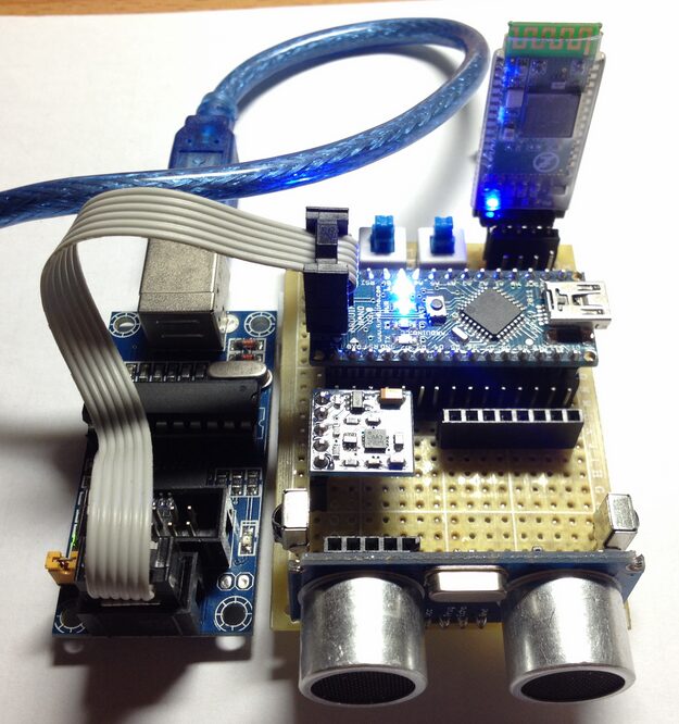
As shown in the figure below, since the USB to serial converter on my Arduino Nano control board was burned out due to a short circuit in a previous light-seeking car experiment, I used a USBtinyISP programmer specifically designed to burn the Bootloader onto the Arduino minimal system board. After testing, all modules worked normally, so the next step was to assemble the robot and write and debug the code.
4. Principles
4.1 Hardware
The following is the hardware system connection diagram of the bionic hexapod robot:
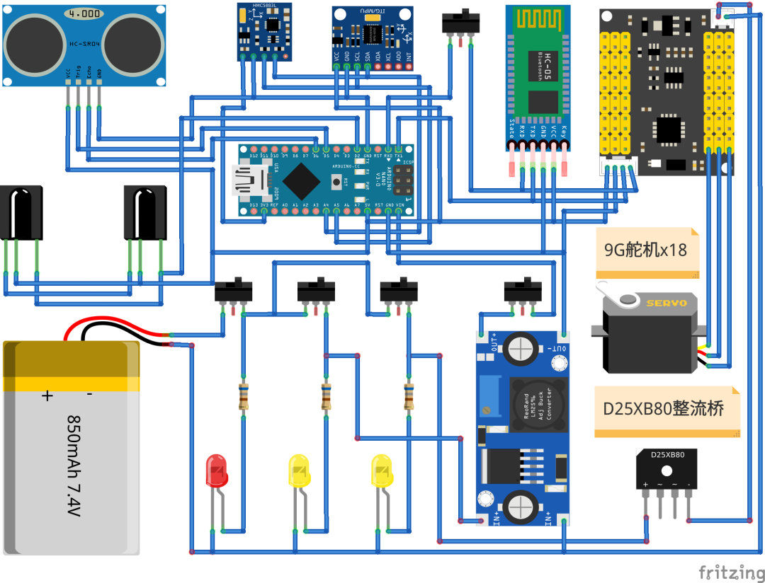
From the above figure, it can be seen that the hexapod robot’s hardware system consists of five main components: servo control, power management, core control, data perception, and data communication. The following is a detailed introduction:
Servo Control
Metal Gear Servo
The specific model of the servo equipped with this hexapod robot is YZW Y09G. Due to the internal motor’s reduction gear set being made of metal, this servo is more expensive than the commonly used plastic gear servos like the SG90, but its performance is outstanding. The standard input voltage range for this servo is 4.8v to 6.0v (slightly over 6v is also acceptable), and the torque range is between 1.3kg/cm to 1.6kg/cm. After testing, the combined torque of the eighteen servos can basically meet the demands of supporting the robot’s body and related loads like the lithium battery. Of course, due to limited positioning accuracy, the servos will have control dead zones. My solution was to eliminate this mechanical structural error through software compensation, allowing the robot to reach the intended target position as accurately as possible.
Servo Control Board
The servo control board, as the name suggests, is a circuit board used to control multiple servos. Since writing programs to output multiple PWM control signals from a microcontroller is quite complex for most robotics enthusiasts, experts have developed convenient servo control boards by packaging the MCU and related peripheral circuits together. Additionally, servo control boards generally come with PC-side debugging software, allowing users to precisely and in real-time control the servo’s rotation angle by dragging sliders on the software interface after establishing serial communication. The programmed actions can also be combined into action groups and downloaded to the servo control board’s chip for storage, laying the foundation for later core control to call them via serial communication. This hexapod robot project uses an early version of a 24-channel servo control board developed by Lazy Cat, with specific usage methods outlined in the 24-channel servo control board user manual.
Power Management
Power management is arguably the most important module in the robot’s hardware control system aside from the core control, as the robot can still move around even if the sensors fail, but if the power part fails, the robot is just a stationary model. This hexapod robot project uses eighteen servos as joint actuators, so although the power consumption of the 9G servos is significantly lower than that of standard servos, the total current required by eighteen servos is still quite impressive. After some consideration, I ultimately chose a lithium battery pack with parameters of 7.4v850mAh as the power source for the robot, which meets the power needs of the hexapod robot.
In addition to the lithium battery power supply, the hardware system connection diagram above also shows two buck circuits. One buck circuit uses an L2596 DC-DC module to reduce the voltage from one power source to a standard 5V to power the Arduino Nano main control board, while the other uses a D25XB80 high-power rectifier bridge, which has a maximum reverse voltage rating of 800V and a rated forward current of 25A. When the lithium battery pack is fully charged (the voltage of a fully charged 7.4v lithium battery pack is about 8.4v), connecting a D25XB80 can reduce the voltage to approximately 6.9v. Tests have shown that it can power the 24-channel servo control board and eighteen servos without any issues.
Finally, to facilitate controlling the input of the lithium battery power supply and the output of the bucked power supply, I connected three switches in parallel, each with an LED light added to indicate whether the power is on or off. For more information on power management, please refer to Lazy Cat’s blog post analyzing the power of the hexapod robot.
Core Control
The core control is mainly responsible for analyzing the data feedback from the sensors and sending action commands to the servo control board, indirectly driving the servos to run to specified angles. In this project, I used the Arduino Nano as the core control, which is compact and has a wealth of development tutorials and device driver libraries, making it easy to use.
Data Perception
The data perception module mainly includes the HC-04 ultrasonic distance sensor, HMC5883L electronic compass sensor, MPU6050 inertial measurement sensor, and infrared receiver. The ultrasonic distance sensor helps the hexapod robot avoid obstacles directly in front of it, while the infrared receiver, along with a common mini infrared remote control, forms the entire remote control system of the hexapod robot. The infrared receiver can receive infrared signals modulated with a 38kHz carrier frequency and send the decoded data to the Arduino Nano for processing. The HMC58883L and MPU6050 sensors are primarily used for the hexapod robot’s motion perception. By collecting their data and performing simple fusion processing, we can obtain the robot’s spatial position relationship, thus providing data support for correcting the robot’s path deviations during movement. However, due to limited development time, this part has not been addressed yet.
Data Communication
Data communication includes infrared communication, serial communication, and Bluetooth communication. The infrared communication has been briefly introduced in the data perception section above, where data is encoded or decoded using the NEC encoding format and transmitted via infrared signals to complete the transmission of remote control command data. Serial communication is mainly used between the core control and the servo control board. According to the data format specified by the servo control board, the core control can send commands to control one or multiple servos to rotate to designated positions. Finally, Bluetooth communication allows software on the PC side to establish a wireless connection with the servo control board, facilitating the debugging of the hexapod robot’s actions.
4.2 Software
Core Libraries
hexapod_bionic_robot.h
This header file defines the HexapodBionicRobot class, which declares core functions for the robot’s obstacle avoidance, infrared coding information processing, ultrasonic distance measurement, and movement of the robot body, among others.
#ifndef HEXAPOD_BIONIC_ROBOT_H
#define HEXAPOD_BIONIC_ROBOT_H

#include <Arduino.h>
#include <IRremote.h>

#define PIN_IR      2
#define PIN_TX      3
#define PIN_RX      4
#define PIN_TRIG    5
#define PIN_ECHO    6
#define PIN_LED     13
#define DIR_INIT    1
#define DIR_STOP    1
#define DIR_FRONT   2
#define DIR_BACK    3
#define DIR_LEFT    4
#define DIR_RIGHT   5
#define MODE_REMOTE 25
#define MODE_AUTO   26
#define RADIX       10
#define RUNTIME     2400
#define TIMEOUT     30000

class HexapodBionicRobot
{
public:
    HexapodBionicRobot(IRrecv *ir_receiver, decode_results *ir_results);
    void avoidFrontObstacle(void);
    void handleInfraredInformation(void);
    void handleUltrasonicDistance(void);
    void moveRobotBody(uint8_t direction, uint8_t times);
    uint32_t getInfraredInformation(void);
    float getUltrasonicDistance(void);
private:
    int             mode_flag_;
    float           duration_;
    float           distance_;
    IRrecv         *ir_receiver_;
    decode_results *ir_results_;
};

#endif // HEXAPOD_BIONIC_ROBOT_H
hexapod_bionic_robot.cpp
This source file implements all the functions declared in the HexapodBionicRobot class. The getInfraredInformation() function calls the official IRremote library to retrieve the infrared codes sent by the remote control in real-time, while the handleInfraredInformation() function compares the obtained infrared codes with pre-defined ones, jumping to the corresponding code block for processing (movement of the robot forward, backward, left, right, and switching between remote and automatic modes). The program will also call the avoidFrontObstacle() function to determine if there are obstacles close to the robot’s body during remote control movement. If the distance is below a predetermined threshold, the robot will automatically retreat or stop to avoid the obstacle.
#include "hexapod_bionic_robot.h"

#define DEBUG 1

HexapodBionicRobot::HexapodBionicRobot(IRrecv *ir_recviver,
                                       decode_results *ir_results)
    : ir_receiver_(ir_recviver),
      ir_results_(ir_results)
{
    pinMode(PIN_LED, OUTPUT);
    pinMode(PIN_TRIG, OUTPUT);
    pinMode(PIN_ECHO, INPUT);

    mode_flag_ = MODE_REMOTE;

    duration_ = 0.0;
    distance_ = 0.0;
}

void HexapodBionicRobot::avoidFrontObstacle(void)
{
    float distance = getUltrasonicDistance();
    Serial.println(distance);

    if (distance == false) {
        return ;
    }
    else if (distance <= 2.5) {
        moveRobotBody(DIR_STOP, 2);
    }
    else if (distance <= 5.0) {
        moveRobotBody(DIR_BACK, 2);
    }
}

void HexapodBionicRobot::handleUltrasonicDistance(void)
{
    float distance = getUltrasonicDistance();

    if (distance == false) {
        return ;
    }
    else if (distance <= 5.0) {
        digitalWrite(PIN_LED, HIGH);
#if DEBUG
        Serial.println("Warning! Distance is too close!!!");
#endif
    }
    else {
        digitalWrite(PIN_LED, LOW);
    }
#if DEBUG
    Serial.print("Distance: ");
    Serial.print(distance);
    Serial.println("cm");
#endif
    delay(100);
}

void HexapodBionicRobot::handleInfraredInformation(void)
{
    float distance = 0.0;
    uint32_t ir_results = getInfraredInformation();

    if (ir_results == false) {
        return ;
    }
    else {
#if DEBUG
        Serial.print("Infrared code: ");
        Serial.println(ir_results, HEX);
#endif
        if (ir_results == 0XFF629D) {
            mode_flag_ = MODE_REMOTE;
        }
        else if (ir_results == 0XFFE21D) {
            mode_flag_ = MODE_AUTO;
        }

        if (mode_flag_ == MODE_REMOTE) {
            digitalWrite(PIN_LED, LOW);
            if (ir_results == 0xFF02FD) {
                moveRobotBody(DIR_FRONT, 2);
                delay(RUNTIME);
            }
            else if (ir_results == 0xFF9867) {
                moveRobotBody(DIR_BACK, 2);
                delay(RUNTIME);
            }
            else if (ir_results == 0xFFE01F) {
                moveRobotBody(DIR_LEFT, 2);
                delay(RUNTIME);
            }
            else if (ir_results == 0xFF906f) {
                moveRobotBody(DIR_RIGHT, 2);
                delay(RUNTIME);
            }
            else if (ir_results == 0xFFA857) {
                moveRobotBody(DIR_STOP, 2);
                delay(RUNTIME);
            }
            avoidFrontObstacle();
        }
        else if (mode_flag_ == MODE_AUTO) {
            digitalWrite(PIN_LED, HIGH);
            while (ir_results != 0XFF629D) {
                ir_results = getInfraredInformation();
                moveRobotBody(DIR_FRONT, 2);
                delay(RUNTIME);
                avoidFrontObstacle();
            }
            mode_flag_ = MODE_REMOTE;
        }
    }
}

void HexapodBionicRobot::moveRobotBody(uint8_t direction, uint8_t times)
{
    char string_direction[5];
    char string_times[5];

    itoa(direction, string_direction, RADIX);
    itoa(times, string_times, RADIX);

    Serial.print("#");
    Serial.print(string_direction);
    Serial.print("G");
    Serial.print(string_times);
    Serial.println("C");
}

uint32_t HexapodBionicRobot::getInfraredInformation(void)
{
    if (ir_receiver_->decode(ir_results_)) {
        ir_receiver_->resume();
        return ir_results_->value;
    }
    else {
        return false;
    }
}

float HexapodBionicRobot::getUltrasonicDistance(void)
{
    duration_ = 0.0;
    distance_ = 0.0;

    digitalWrite(PIN_TRIG, LOW);
    delayMicroseconds(10);
    digitalWrite(PIN_TRIG, HIGH);
    delayMicroseconds(10);
    digitalWrite(PIN_TRIG, LOW);

    duration_ = pulseIn(PIN_ECHO, HIGH, TIMEOUT);

    if (duration_ == 0.0) {
        return false;
    }
    else {
        distance_ = duration_ * 0.017;
        return distance_;
    }
}
Test Code
hexapod_bionic_robot_test.ino
The principle of this test code is very simple. First, the setup() function initializes and opens the serial port at a baud rate of 115200, and then the Arduino Nano sends #1G2C (run action group 1 twice) to make the hexapod robot stand up. Immediately after, the program enables the infrared receiver, allowing it to receive infrared codes sent by the remote control. Once initialization is complete, the main program jumps to the loop() function to execute the HexapodBionicRobot class object’s handleInfraredInformation() function to complete the infrared remote control and ultrasonic obstacle avoidance functions.
#include <IRremote.h>
#include <hexapod_bionic_robot.h>

IRrecv         g_ir_receiver(PIN_IR);
decode_results g_ir_results;

void setup()
{
    Serial.begin(115200);
    Serial.println("#1G2C");
    g_ir_receiver.enableIRIn();
}

void loop()
{
    HexapodBionicRobot hexapod_bionic_robot(&g_ir_receiver, &g_ir_results);
    hexapod_bionic_robot.handleInfraredInformation();
}
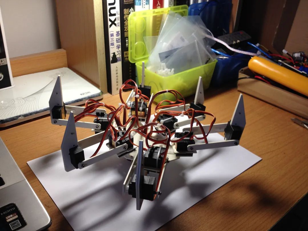
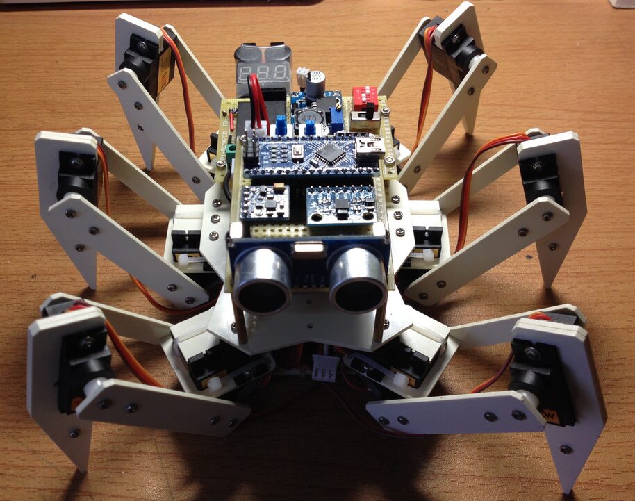
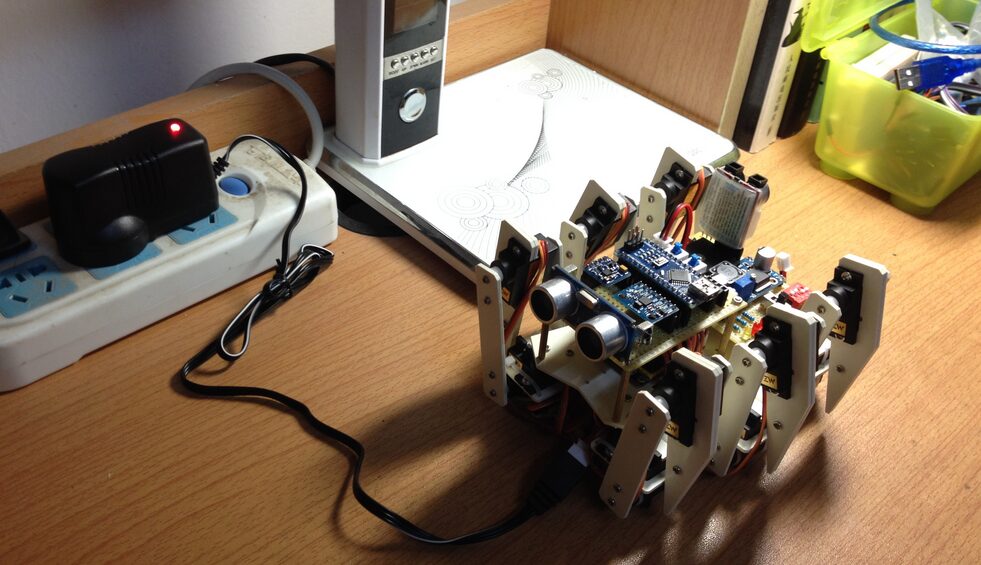
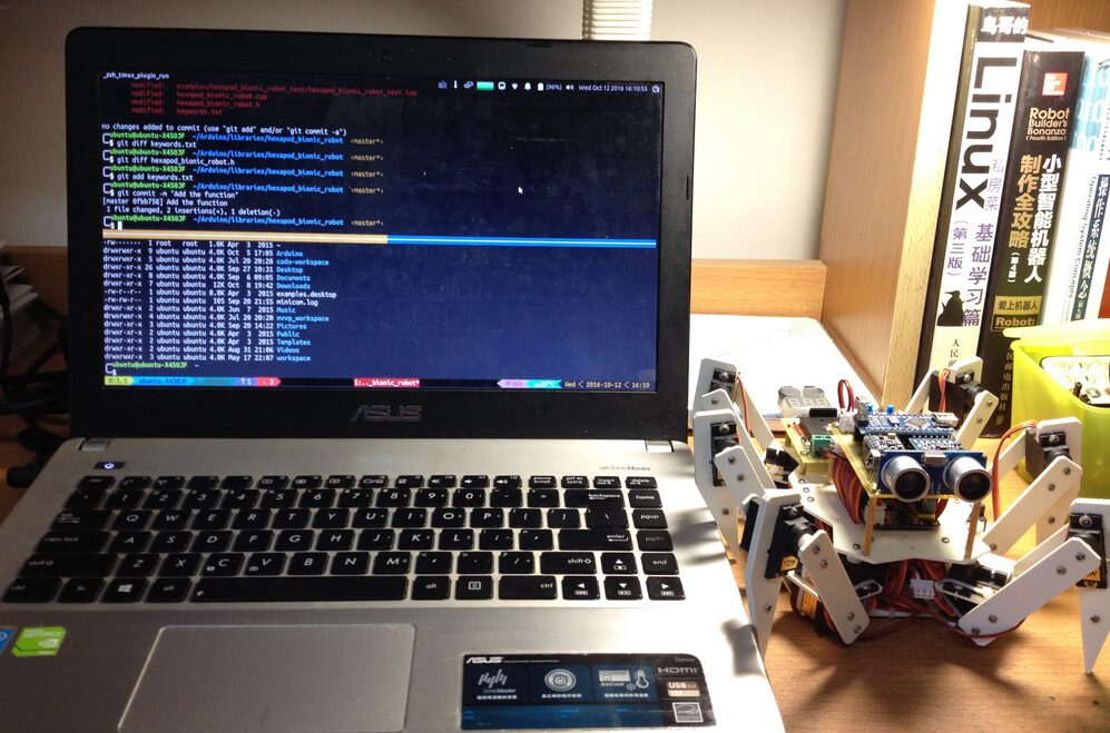
5. Results
Below are the images and test videos of the completed project:

6. Conclusion
Reflecting back, it was after reading the tutorial on the hexapod insect – your next legged mobile robot that I became fascinated with hexapod robots. I never expected that by the time I was about to graduate, I would have the opportunity to complete my own hexapod bionic robot. To be honest, when I first saw the hexapod robot stand up under its own power, I was incredibly excited. Although the servos’ torque was somewhat low, causing slight vibrations in the robot’s limbs when supporting the ground, the eighteen degrees of freedom allowed the hexapod robot to perform many complex movements that other robots cannot. Perhaps this is the charm of multi-legged robots!
However, for beginners in robotics, making a hexapod robot is still significantly more challenging than building a wheeled robot, and it also requires a considerable investment of time and money. If you have strong hands-on skills and technical expertise and think, like me, that hexapod robots are very cool, you can also try to make your own hexapod robot and expand it with more interesting features (for example, I added the MPU6050 and HMC5883L modules for motion perception and correction, but unfortunately could not implement it due to time constraints). Finally, I would summarize three key factors needed to successfully create a hexapod robot: 1. A heartfelt love for the project from start to finish; 2. Professional knowledge in mechanics, electronics, and software; 3. Persistent effort to achieve the final goal!