In regular applications, KUKA robots, riveting equipment, laser welding, and other devices extensively use EtherCAT communication. Below, we will introduce it.
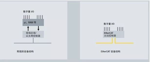
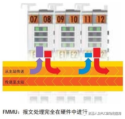
1. EtherCAT protocol processing is entirely done in hardware.
The protocol ASIC can be flexibly configured. The process interface can be expanded from 1 bit to 64 kbyte.
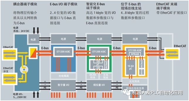
This allows Ethernet to connect directly to terminal modules:
The Ethernet protocol that complies with IEEE 802.3 standards can access various devices without any additional bus. The physical layer in coupling devices is converted from 100BASE-TX or –FX to E-bus to meet the needs of modular devices such as electronic terminal blocks. The E-bus signal type within the terminal block (LVDS) is not proprietary; it can also be used for 10 Gbit Ethernet. At the end of the terminal block, the physical bus characteristics are converted back to 100BASE-TX standards.
The integrated Ethernet MAC on the motherboard is sufficient to be used as hardware in master devices. DMA (Direct Memory Access) is used to transfer data to the main memory, relieving the CPU of the burden of accessing network data. Beckhoff’s multi-port plug-in card employs the same principle, bundling up to 4 Ethernet channels in a single PCI slot.
2. EtherCAT performance
EtherCAT has reached a new level of network performance.
The update time for 1000 I/O is only 30 µs, which includes the I/O cycle time. A single Ethernet frame can exchange up to 1486 bytes of process data, almost equivalent to 12000 digital inputs and outputs, and it takes only 300 µs to transmit this data.
Communication with 100 servo axes is executed every 100 µs. In this cycle time, the actual position and status of all axes with command values and control data can be updated, and distributed clock technology ensures that the synchronization deviation of the axes is less than 1 microsecond.
The ultra-high-performance EtherCAT technology can achieve control concepts that traditional fieldbus systems cannot reach.
Thus, ultra-fast control loops can also be formed through the bus. Functions that previously required local dedicated hardware support can now be mapped in software. The enormous bandwidth resources allow status data to be transmitted in parallel with any data. EtherCAT adapts communication technology to the ultra-strong computing power of modern industrial PCs, making the bus system no longer a bottleneck for control concepts. Distributed I/O may operate faster than most local I/O interfaces.
This network performance advantage is particularly evident in small controllers with relatively moderate computing power. EtherCAT’s cycle time is so short that it can complete tasks between two control cycles. Therefore, the controller can always obtain the latest input data; outputs are addressed with minimal delay. Without enhancing its own computing power, the controller’s response behavior can be significantly improved.
Thanks to the integration of slave hardware and the direct memory access of the master network controller, the entire protocol processing is done in hardware, making it completely independent of the protocol stack, CPU performance, or software implementation.
The update time for 1000 I/O is only 30 µs, which includes the I/O cycle time.
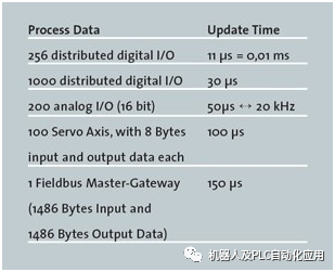
A single Ethernet frame can exchange up to 1486 bytes of process data, almost equivalent to 12000 digital inputs and outputs, and it takes only 300 µs to transmit this data.
Communication with 100 servo axes is also very fast: all axes with command values and control data can be updated in their actual position and status every 100 µs, and distributed clock technology ensures that the synchronization deviation of the axes is less than 1 microsecond. Even when ensuring this performance, the bandwidth is still sufficient for asynchronous communication, such as TCP/IP, downloading parameters, or uploading diagnostic data.
The ultra-high-performance EtherCAT technology can achieve control concepts that traditional fieldbus systems cannot reach. EtherCAT adapts communication technology to the ultra-strong computing power of modern industrial PCs, making the bus system no longer a bottleneck for control concepts. Distributed I/O may operate faster than most local I/O interfaces. The principles of EtherCAT technology are flexible and not limited to 100 Mbps communication rates; it can even be extended to 1000 Mbps Ethernet.
3. EtherCAT topology
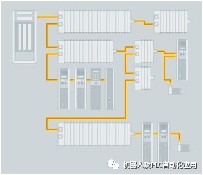
Bus, tree, or star: EtherCAT supports almost any type of topology.
Thus, the bus structure or linear structure named after the fieldbus can also be used for Ethernet and is not limited by the number of cascaded switches or hubs.
The most effective system wiring method is to topologically combine linear, branch, or tree structures. Since the required interfaces already exist in many devices such as I/O modules, no additional switches are needed.
Of course, traditional Ethernet-based star topologies can still be used.
Different cables can also be chosen to enhance wiring flexibility: flexible, cost-effective standard Category 5 Ethernet cables can transmit signals in 100BASE-TX mode, with a maximum cable length of 100 m between two devices.
Complete combinations of different Ethernet connections (such as different fiber optics and copper cables) can also be achieved through switches or media converters.
Signal variables can be selected individually based on the spacing of each cable. Since the number of connected devices can reach up to 65535, the network capacity is almost unlimited.
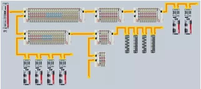
EtherCAT uses full-duplex Ethernet physical layers, and slaves may have two or more ports. If a device does not detect other devices downstream, the slave controller will automatically shut down the corresponding port and return the Ethernet frame. Due to these characteristics, EtherCAT supports almost all network topologies, including bus, tree, or star, and the commonly used bus topology in fieldbuses can also be used in Ethernet.
The topology of EtherCAT can be combined arbitrarily with network lines, branches, or short lines (stub). Devices with three or more Ethernet interfaces can act as splitters, and it is not necessary to use network switches. Due to the use of 100BASE-TX Ethernet physical layer, the distance between two devices can reach 100 meters, and a single EtherCAT segment can have up to 65535 devices. If the EtherCAT network uses a ring topology (the master device needs two communication ports), this network also has cable redundancy capabilities.
4. EtherCAT supports hot plugging
Many applications require changing I/O configurations during operation. For example, processing centers with constantly changing demands, tool systems equipped with sensors, intelligent transport systems, flexible workpiece actuators, or printing machines with individually switchable printing units. The EtherCAT system’s protocol structure has already considered these needs: the hot plugging function can connect or disconnect various parts of the network or perform rapid reconfiguration, providing flexible responsiveness to changing configurations.
5. EtherCAT security: Safety over EtherCAT
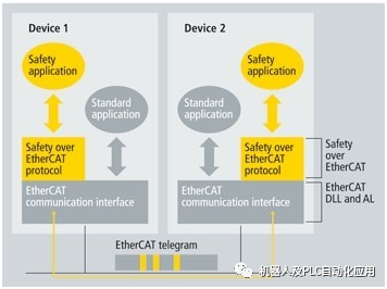
EtherCAT has an enhanced version of the protocol called Safety over EtherCAT, which can conduct safety-related communication and general control communication on the same network. This safety communication is based on EtherCAT’s application layer and does not affect the underlying communication protocol. Safety over EtherCAT has been certified through IEC 61508 and meets the requirements of Safety Integrity Level (SIL) 3.
To achieve EtherCAT safety data communication, we have opened the Safety over EtherCAT protocol. The EtherCAT safety communication protocol has been publicly released within the ETG organization. This protocol has been certified by the German Technical Inspection Agency (TÜV) to meet the IEC61508 defined SIL3 level requirements. Implementing the EtherCAT safety protocol on devices must meet the safety target requirements, and the corresponding product-related requirements must also be considered.
EtherCAT is used as a single channel for transmitting both safety and non-safety data. The transmission medium is considered a “black channel” and is not included in the safety protocol.
Safety data packets in EtherCAT process data include safety process data and the required data backup. This “container” is safely parsed at the application layer of the device. Communication remains a single channel. This complies with the model in IEC61784-3 annex A. Thus, this safety protocol can also be transmitted through other communication systems, backplanes, or WLAN. The transmission cycle can be shortened as required without affecting the residual error rate. Safety data cyclic exchange between the EtherCAT master and slave is monitored by a watchdog timer. One master can establish and monitor connections with multiple different slaves.
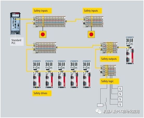
Safety components can be used anywhere in automation systems. Different scales of local input and output components can be used in the system. Additional inputs and outputs can be extended using safety or non-safety bus terminals as needed. Safety logic is also embedded in the network. This allows standard PLC without safety extensions to continue processing control tasks. The local safety logic required for safety input and output functions is implemented by intelligent safety bus terminals. This saves the cost of expensive safety PLCs and allows for flexible logic functions to be tailored to current tasks. Only the safety EtherCAT master and the assigned safety slaves are routed through non-safety standard PLCs.
The protocol has no restrictions on safety data length, communication medium, or baud rate.
EtherCAT is used as a “black channel”, meaning the communication system has no role in safety processing.
The protocol has been certified to comply with the IEC61508 defined SIL3 level.
Products offering EtherCAT safety functionality have been on the market since 2005.
6. EtherCAT diagnostics
Practical experience in fieldbus systems shows that effectiveness and trial operation time critically depend on diagnostic capabilities. Only by quickly and accurately detecting faults and clearly indicating their location can faults be quickly eliminated. Therefore, during the development of EtherCAT, special emphasis was placed on strengthening diagnostic features.
The diagnostic capability of the network is crucial for improving network reliability and shortening debugging time—thus reducing overall costs. Only by quickly and accurately detecting faults and clearly indicating their location can faults be quickly eliminated. Therefore, during the development of EtherCAT, special emphasis was placed on strengthening diagnostic functions.
During the trial operation, the actual configuration of nodes such as drives or I/O terminals needs to be matched with the specified configuration, and the topology also needs to match the configuration.
Since the integrated topology identification process has extended to various terminals, this check can be performed not only during system startup but also during network auto-reading (configuration upload).
Bit errors occurring during data transmission can be detected by evaluating the CRC check on each device—32-bit CRC polynomial’s minimum Hamming distance is 4. In addition to breakpoint detection and localization, the EtherCAT system’s protocol, physical layer, and topology can also monitor the quality of each transmission segment separately. Automatic evaluation associated with error counters can also accurately locate critical network segments. Moreover, for gradual or sudden error sources such as electromagnetic interference, connector damage, or cable damage, even if they have not exceeded the network’s self-recovery capability, they can still be detected and located.
————————–end—————————

Good job, let’s take a small step forward every day.