An Overview of ADC Working Principles
►►►
Definition
ADC, or Analog-to-Digital Converter, is primarily responsible for converting continuously varying analog signals into digital signals, enabling digital systems (such as Central Processing Units (CPUs) and Microcontrollers (MCUs)) to efficiently process and analyze the transmitted information.
Analog signals refer to information transmitted through continuously varying physical quantities, such as temperature, humidity, pressure, voltage, and current. The analog signals collected by the ADC module are specifically represented as continuously varying voltage or current, with values that fluctuate continuously within a specific range. The advantages and disadvantages of analog signal transmission are as follows:
Advantages:
1) High precision resolution, theoretically reaching infinity under ideal conditions;
2) Simpler processing of physical quantities compared to digital signals;
3) No quantization error, allowing for an accurate reflection of the actual values of physical quantities;
4) Analog signals are intuitive and easier to implement in practice.
Disadvantages:
1) Analog signals are relatively weak and easily affected by noise;
2) Limited transmission range, only capable of short-distance transmission;
3) Poor anti-interference capability, often affected by noise during transmission;
4) Lower confidentiality, making the content of communications easily eavesdropped.
Digital signals consist of a series of discrete numbers, with finite values typically represented in binary code (0 and 1). The advantages and disadvantages of digital signal transmission are as follows:
Advantages:
1) Excellent anti-interference capability. Digital signals, presented in binary form, are less affected by interference compared to the continuous variations of analog signals, allowing for more effective resistance to external disturbances during transmission and processing.
2) Easier to compress and process. Using encoding and compression algorithms, digital signals can reduce data volume, saving bandwidth and space during transmission and storage. Additionally, digital signal processing (DSP) technology can efficiently implement algorithms and conduct signal analysis.
3) Low transmission loss. During transmission, digital signals can counteract losses through amplification and compensation, improving signal quality. Furthermore, error correction coding techniques can ensure data accuracy through error detection and correction mechanisms.
4) Good compatibility. Digital signals can connect with various devices and systems through digital interfaces, enabling interoperability among different digital signals.
Disadvantages:
1) Higher processing delay. Digital signals experience some delay during Digital-to-Analog Conversion (DAC) and Analog-to-Digital Conversion (ADC), which may pose issues for applications requiring real-time performance, such as audio transmission and communication systems.
2) Limited precision. The precision of digital signals is influenced by the sampling rate, as they can only be represented by discrete values, limiting their precision. In high-precision applications, a higher sampling rate and larger data representation range may be required.
►►►
Working Principle
The conversion of analog signals to digital signals by an ADC involves sampling, holding, quantizing, and encoding. Sampling and holding are performed in the sample-and-hold circuit, while quantization and encoding occur within the ADC.
Sampling refers to the ADC extracting samples of the continuously varying analog signal at specific time intervals, allowing for the distortion-free restoration of signal waveform information under limited sampling rate conditions. The sampling frequency determines the number of samples collected per second, typically measured in Hz. In ADC sampling, for a sine wave, at least two points must be collected per cycle to accurately restore it. If the sampling frequency matches the period of the measured signal, only one point can be collected per cycle, resulting in a straight line rather than the original signal waveform, leading to distortion.
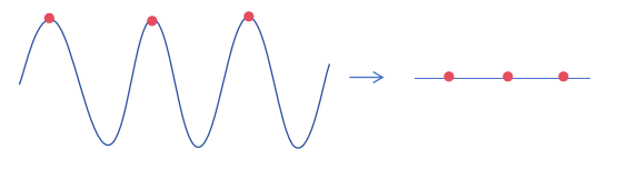
Only when the sampling frequency is twice that of the measured signal can the highest and lowest points of each cycle be captured, allowing the connected waveform to correspond to the original signal waveform and avoid distortion.

The sample-and-hold process of the ADC maintains the collected analog signal at a constant state for a period, facilitating the subsequent conversion of the analog signal to a digital signal. The circuit that supports this process is the Sample-and-Hold Amplifier (SHA). The working mechanism of the sampling ADC is as follows: in sampling mode, the SHA performs sampling operations on the signal; during hold mode, the signal is maintained at a constant state. By adjusting the timing, the subsequent ADC encoder can perform Analog-to-Digital conversion (A-to-D conversion) on the held signal during the hold time. Since the signal remains almost unchanged in hold mode, the ADC can handle rapidly changing high-frequency signals, with its upper frequency limit determined not by the encoder but by the performance metrics of the SHA, such as aperture jitter, bandwidth, and distortion.
The signal obtained during the sample-and-hold phase is a discrete analog signal. To convert the analog signal into a digital signal, the output voltage from the sample-and-hold circuit must be mapped to corresponding discrete levels in a specific manner. This conversion process is known as numerical quantization, commonly referred to as quantization. For example, a 3-bit ADC corresponds to 8 quantization levels:
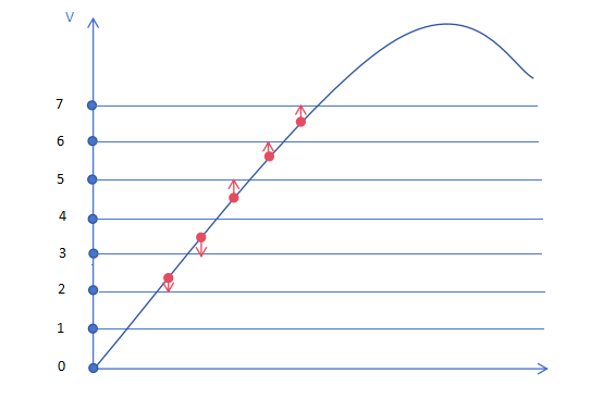
The encoding process involves representing the quantized values according to specific rules using corresponding codes to depict the waveform of the analog signal. Binary codes:
Level 0 (0V) → 000
Level 1 (1V) → 001
Level 2 (2V) → 010
Level 3 (3V) → 011
Level 4 (4V) → 100
Level 5 (5V) → 101
Level 6 (6V) → 110
Level 7 (7V) → 111
Thus, according to the five sampling points shown, they correspond to 010, 011, 101, 110, and 111. This binary code can be directly recognized and processed by digital systems (such as CPUs), completing the transformation from a continuously varying analog signal to a discrete digital sequence.
✦
✧
END
✦