
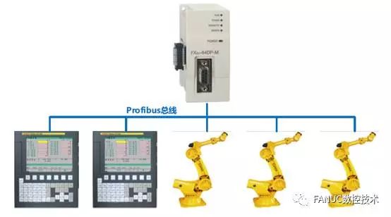
PROFIBUS is an international, open, fieldbus standard that is independent of device manufacturers. The transmission speed can be selected from 9.6 kbaud to 12 Mbaud, and when the bus system starts, all devices connected to the bus should be set to the same speed. It is used for factory automation at the workshop level for monitoring and communication with field devices, enabling decentralized digital control and field communication networks from the field device layer to the workshop level, thus providing a feasible solution for integrated factory automation and intelligent field devices. It consists of three compatible parts: PROFIBUS-DP (Decentralized Periphery), PROFIBUS-PA (Process Automation), and PROFIBUS-FMS (Fieldbus Message Specification). Among them, PROFIBUS-DP is applied at the field level and is a high-speed, low-cost communication used for communication between device-level control systems and decentralized I/O. The bus cycle is generally less than 10 ms, using protocol layers 1 and 2 and user interfaces to ensure fast and effective data transmission; PROFIBUS-PA is suitable for process automation and allows sensors and actuators to connect on a shared bus, applicable in intrinsically safe areas; PROFIBUS-FMS is used for workshop-level monitoring networks, which is a token-structured real-time multi-master network used for communication between controllers and intelligent field devices, as well as information exchange between controllers. It mainly uses a master-slave mode and typically exchanges data with the drive periodically.
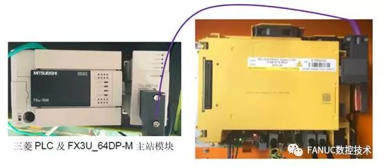
The master-slave structure for this debugging is as follows: Mitsubishi FX3u-64DP-M module as the master station, FANUC 0i-MD and other joint robots as the slave stations.
Debugging Process 1 Function Selection
0i-D is optional, 0i-Mate cannot be used.
PROFIBUS hardware and software order numbers
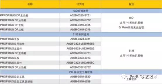
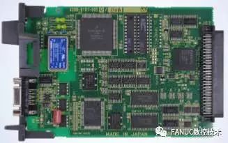
PROFIBUS Board
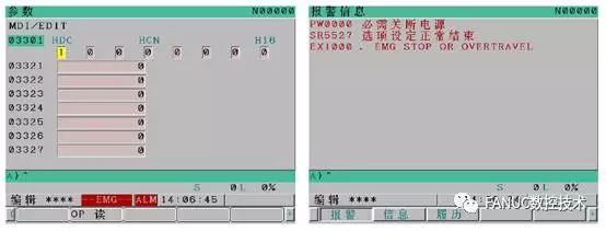
Debugging Process 2 Software Function Addition
Apply for function addition based on system serial number and ID information, rename the file to CNCOPSET.TXT. Import OP read under the parameter screen. Check diagnostic number DGN.1147#0=1, function addition successful.
Software Function Addition
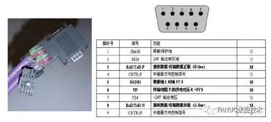
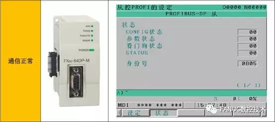
Debugging Process 3 Hardware Connection
Hardware connection includes the installation of the CNC expansion board, making plugs, and connecting to the master station.
Hardware Connection Diagram

Debugging Process 4 Software Settings
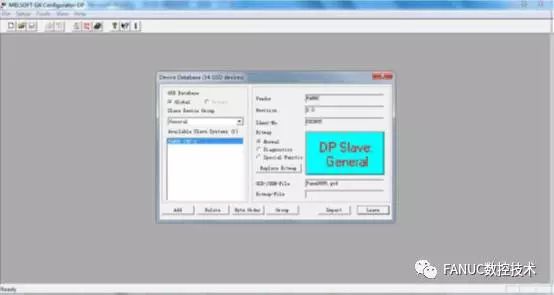
Generally, when the manufacturer of the slave module is different from that of the master PLC, it is necessary to install the GSD file of the slave module when configuring the master station. GSD (General Station Description) file can be seen as the driver file for PROFIBUS-DP products, describing the functional parameters of the products. PROFIBUS configuration tools can integrate their devices into the same bus system based on the GSD files provided by manufacturers. The FANUC 0i-MD used as a slave in this debugging needs to provide the GSD file to the master station. (0i-D products can use Fanuc0805.gsd from the PROFIBUS SETTING installation package). Through this file, the master station can obtain the slave’s device version number, define supported protocols, device types, device hardware and software version numbers, ID, supported baud rates, information length, diagnostic information meanings, and optional ranges of input/output modules.
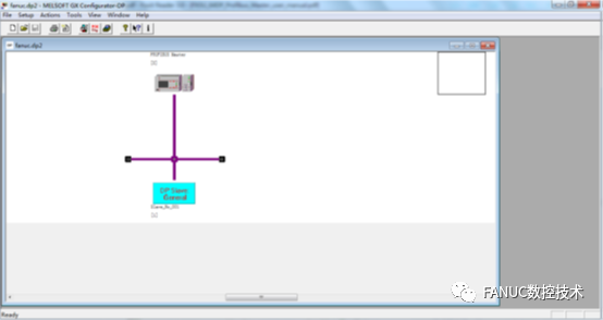
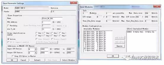
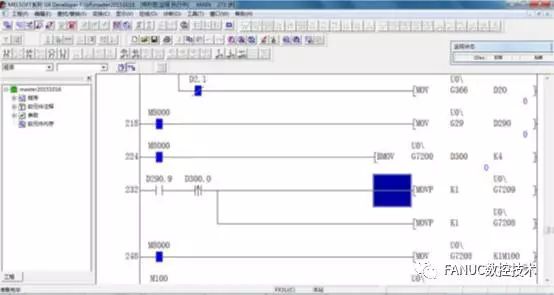
This debugging case uses Mitsubishi’s GX Configurator DP software for setting the PROFIBUS configuration parameters. After the settings are completed, the configuration file is downloaded to the master module.
Profibus Configuration Settings
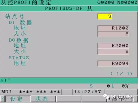
Debugging Process 5 Setting PROFIBUS Slave Station Number and Address Allocation on CNC System:
Station Number and Address Allocation
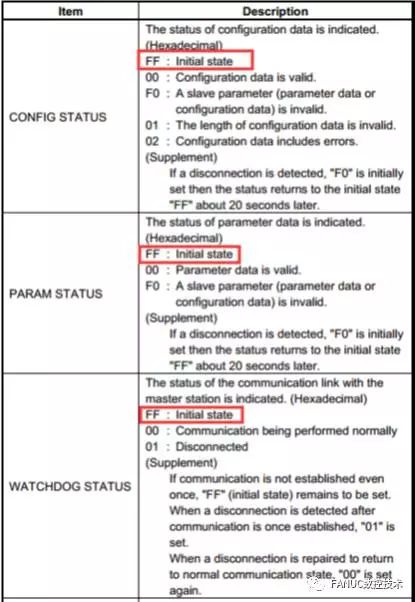
After completing the above operations, toggle the master module’s run switch to conduct communication testing. During this debugging process, there was initially no normal communication, and the master module indicator showed a communication error. Checking the status screen, it was found that the configuration, parameters, and watchdog status were all “FF”, indicating invalid parameter configuration. The following aspects were checked:
1) Check the terminal resistance selection switch of the Profibus plug, all set to “ON” (for normal series connection, the first and last devices are set to ON, and the middle devices are set to OFF), so the terminal resistance setting is not an issue.
2) Replaced the communication cable, but still unable to connect.
3) Check the GX Configurator DP settings and found that the address allocation used the D address; after changing it to R address, communication was normal.

For address allocation and slave status explanation, refer to the “B-64403EN_01_PROFIBUS-DP Board Connection Manual”.

Debugging Process 6 Communication Testing
IO operations can be performed on the master PLC to check whether the system PMC mapping address bits have corresponding actions. Other robot and machine tool linkage actions can be improved in the PLC later.
This article is reproduced from: FANUC CNC Technology
Share it with your friends; they are also looking for this article!
Long press the QR code, follow the WeChat account, and carry the CNC manual with you!

Query CNC alarms, parameters, technical data, manuals via WeChat,
Simple, convenient, and fast,
Supports mainstream CNC brands,
Query speed is much faster than flipping through books,
No more carrying heavy paper manuals around,
It’s truly a great helper for CNC technicians!