Follow the association or click to read the original text to participate in the home appliance survey
Cast your most precious vote
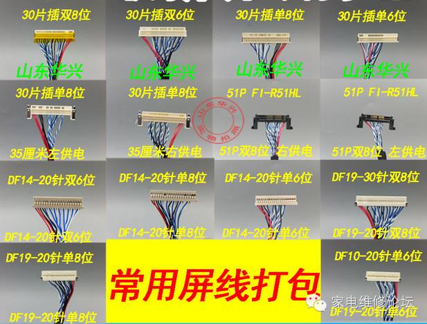
1. Types of LCD Screen Interfaces and Cables
The LCD screen interfaces are divided into 60HZ, 120HZ, and even higher frequencies like 200HZ and 240HZ. Different frequency driver boards are required, with main interfaces including 30PIN flat, 30PIN buckle, 51PIN buckle, and 51PIN and 41PIN double buckle for 120HZ screens.
Types of screen cables: single 6, double 6, single 8, double 8. Here, 6/8 refers to the number of signal groups in the screen cable. 4 groups are single 6, 8 groups are double 6, 5 groups are single 8, and 10 groups are double 8. Higher configurations are rare in the market. Note: Screen cables are divided into left single/double 8, or right single/double 8, indicating different power supply positions and signal order differences.
2. LCD Screen Resolutions
1024X768 – Commonly found on 15-inch monitors
1280X1024 – Commonly found on 17-inch/19-inch 4:3 monitors
1366X768 – Commonly found on 15.6-inch low-resolution screens, 18.5-inch, 26-inch, 31.5-inch (commonly 32-inch TVs)
1440X900 – Commonly found on 19-inch monitors, with special resolutions like 1680X1050 or 1920X1200.
1920X1080 – Commonly found on 37-inch, 39-inch, 40-inch, 42-inch, 46-inch, 50-inch, 55-inch, 60-inch, 65-inch, etc.
3. LCD Screen (Power Supply via Cable)
Laptop screens typically require 3.3V, monitor screens require 5V, and TV screens generally require 12V. Special 27-inch screens may have a 5V power supply.
4. Approach to Screen Testing
When acquiring an LCD screen, first confirm the resolution, power supply, and backlight voltage (LCD TVs are typically 24V). After confirming these aspects, select the driver board and connect all power lines and screen cables (if uncertain, use a digital multimeter to measure each data line; the diode setting should show a resistance around 100 ohms, and each group should not exceed 10 ohms in difference. Ensure the power supply red line is not connected to ground). After confirming everything is okay, power on and flash the corresponding resolution software. Boards with pre-flashed software do not require this step.
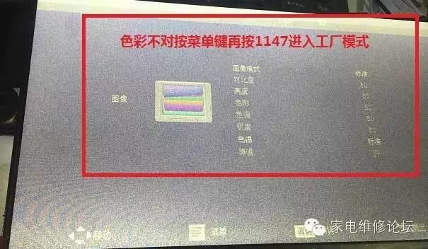
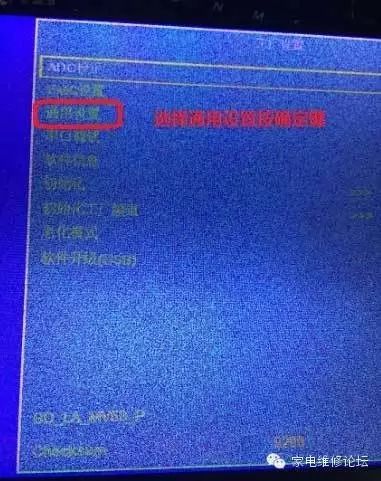
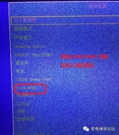
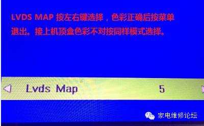
5. TV Board Color Issues After Software Flashing, adjust as follows:
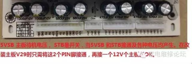
6. LCD TV Power Switch PIN Definitions
When using high-definition driver boards, simply connect the corresponding defined pins.
7. High Voltage Board Interface Definitions
24V GND switch BLON brightness adjustment ADJ or DIM
Connect 24V to the power board and GND to the power board, with the switch and brightness adjustment connected to the corresponding positions on the main board. If brightness is too low during modification, the brightness adjustment can be removed (disconnected).
8. Diagnosing LCD TV Failures
First, confirm whether the power supply is normal, whether the main board can power on, and whether the screen power supply is delivered.
9. Modifying the Remote Control Receiver
Adding a 4.7UF/16V capacitor to the 5V power pin can greatly improve remote control effectiveness. Connect the corresponding pin to the main board, with the red LED, green LED, and the middle pin as GND.
Original text: http://www.jdwx.info/thread-565824-1-1.html
For related cooperation, please add WeChat number:caiman39
Welcome to submit articles to discuss the development of the home appliance service industry!