TechGear
The ECU is the core of the electronic control system. It is essentially a microcomputer or microcontroller that receives signals from sensors on one hand, processes this information, and sends corresponding instructions to control the actions of actuators on the other hand.
Sensors are components that perceive information, responsible for providing the ECU with the operational status of various systems and the vehicle’s operating conditions; actuators are responsible for executing the instructions issued by the ECU, serving as the implementers of those instructions.
For diagnosing automotive circuits, Teacher H has summarized the following five points:
-
Types of input signals from sensors and measurement methods;
-
Analog driving of actuators and judgment of component quality;
-
System control strategies;
-
Diagnostic methods for network communication;
-
Measurement methods for harnesses and connectors.
Repair technicians generally have a habit of digging deep to understand the root cause of each fault. When it is confirmed that the input signal is normal but there is no output control, it can generally be confirmed that there is a problem inside the ECU. Besides replacing the ECU, many repair technicians also want to know which internal component of the ECU is faulty, leading to such a failure.
To understand the internal circuits of the automotive ECU, one must not only understand the principles of various logic circuits and electronic components but also the methods for analyzing complex circuits. This can indeed be a bit challenging for technicians who deal with engines and transmissions daily.
However, even those who specialize in ECU repairs may not necessarily understand circuit analysis, and they may not fully grasp automotive principles either. Of course, there are experts who understand both, like Teacher H and Teacher Y from TechGear.
Today, Teacher H will introduce the circuit testing within the ECU, aimed at automotive repair technicians who understand cars but not electronic circuits. Technicians specializing in electronic repairs can treat this as entertainment.
From the repair manual, one can find terminal information for the ECU, definitions of each pin, and all input and output information.
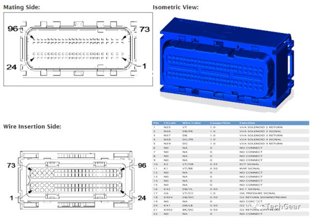
It is important to mention that even though they are all grounds, some are input signals while others are output signals, which everyone needs to clarify.
Similarly, these terminals are also connected to the internal circuits of the ECU. So how are the connections made inside the ECU?
Thanks to the development of electronic technology, the modules contain various integrated circuit chips. Each chip has its own function and role.
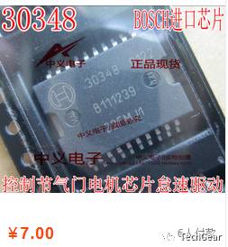
A small chip can handle a lot of information processing; each chip has its own number printed on it, and you can look up the functions of these chips online. Teacher H found an engine ECU from a certain car to demonstrate.
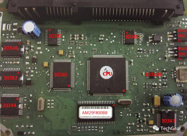
Function of chip 30348: controls the throttle position motor.
When a fault occurs, pressing the accelerator pedal yields no response in engine RPM; idle is unstable.
Function of chip 30382: controls the turbocharger recirculation valve and camshaft adjustment valve.
When a fault occurs, the turbocharger operates poorly, resulting in insufficient engine power; it cannot control camshaft adjustment, causing idle shaking.
Function of chip 30344: controls the fuel injectors, boost pressure limit solenoid, and fuel pump relay coil.
When a fault occurs, the fuel pump relay does not work; the fuel injector does not spray or sprays continuously; the turbocharger has insufficient power.
Function of chip 30397: controls four ignition coils.
When a fault occurs, the ignition coils do not fire.
Function of chip 30380: controls the sensor acquisition module.
When a fault occurs, the vehicle cannot start.
Function of chip 30345: collects oxygen sensor signals and controls fuel injection.
When a fault occurs, black smoke comes out of the exhaust pipe, and shaking occurs at idle.
Function of chip 30343: converts 12V voltage to 5V voltage, controlling the internal power supply of the computer.
When a fault occurs, the ECU cannot function, and all sensors and actuators lack 5V.
Function of AM29F800BB memory: stores standard data.
When a fault occurs, the vehicle cannot start or idles unstably.
If one is not very familiar with the chips, we can use the computer chip parameter measurement comparison method. This is also one of the most efficient methods for ECU repairs.
When performing ECU repair work, a dedicated automotive multi-channel adjustable power supply is required. TechGear has a set specifically for teaching purposes.
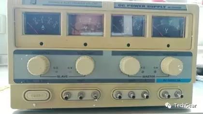
Computer chip parameter measurements include voltage measurements, resistance measurements, and frequency measurements. During repairs, connect only the power supply to the computer’s pins, while measuring the voltage values and resistance values of the main circuits, integrated blocks, transistors, etc., in the faulty ECU against the corresponding voltage values and resistance values of the normal ECU’s chips. This can quickly determine the fault location.
For example, if the fault phenomenon is that the engine can only idle and cannot accelerate. Fault verification: Start the engine, and when pressing the accelerator pedal, the engine RPM remains at 800rpm without change.
Diagnosis process: Use a diagnostic tool to observe the data stream changes.
-
Data stream of the accelerator pedal: when pressing down on the accelerator pedal, the pedal position 1 changes from about 0.6V to 4.2V; pedal position 2 changes from about 0.3V to 2.1V. The signals from the two accelerator sensors change linearly in a two-fold relationship, indicating that the accelerator pedal signal input is normal.
-
Data stream of the throttle: when the accelerator pedal is not pressed, the throttle opening is 3.14%; when the accelerator pedal is pressed, the throttle opening remains 3.14%. Analyzing the throttle data stream shows that the potentiometer data inside the throttle has not changed, and the duty cycle signal for the motor drive has also not changed, indicating that the computer has no output, leading to a judgment of internal ECU failure.
-
Remove the engine computer, open the computer board casing, and supply power to the computer’s power supply terminals, including constant power and ignition switch power. Then connect the negative terminal of the computer. Find the chip controlling the throttle motor (model 30348), and find that pin 2 reads 4.9V, while the normal value should be 0V. The 30348 chip heats up, indicating an internal short circuit. Replace the 30348 chip, and measure pin 2 of 30348 to be 0V. Reinstall the computer and test drive; everything returns to normal.
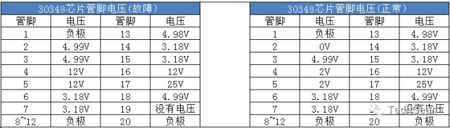
This chip can be purchased for less than 10 yuan on certain platforms. Once this layer of mystery is unveiled, it doesn’t seem so mysterious anymore.
After all, there is a saying that every profession has its own expertise. As automotive repair technicians, one must excel in their field, continuously refine the five points summarized by Teacher H, as diagnosing automotive circuits is a prerequisite. Only after ruling out sensors, actuators, and wiring can there be a possibility of ECU computer repairs.
TechGear’s “Automotive Diagnostics – Automotive Circuits” is a series of courses, including “Circuit Diagnosis,” “Electronic Control and Strategies,” and “The Mysteries of Electronics.”
TG Classroom will focus on real automotive diagnostic techniques, creating a unique automotive diagnostics curriculum that truly teaches you practical diagnostic methods.
To learn more about automotive diagnostic knowledge, please sign up for TechGear courses.
Please scan the QR code below to register.