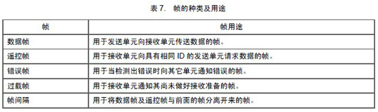
Communication is conducted through the following 5 types of frames.
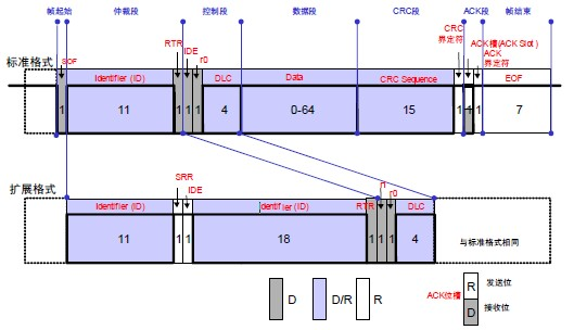
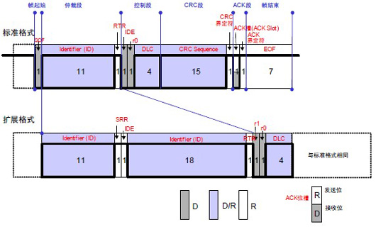
In addition, the data frame and remote frame have both standard and extended formats. The standard format has11 bits identifier (Identifier: hereinafter referred to asID), and the extended format has29 bits ID.
The purposes of various frames are shown in Table 7 and the composition of various frames is illustrated in Figures1~Figure5 below.
Figure1.Composition of Data Frame
Figure 2. Composition of Remote Frame
2. Determination of Priority
In the idle state of the bus, the unit that starts sending messages first gains the right to transmit.
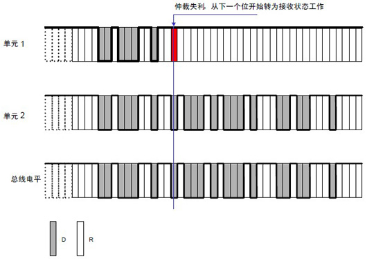
When multiple units start sending simultaneously, each sending unit begins arbitration from the first bit of the arbitration segment. The unit that continuously outputs the dominant level the most can continue to send.
The arbitration process is illustrated as shown.
Figure: Arbitration Process
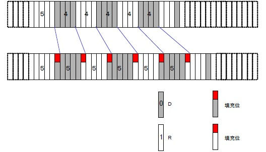
Bit stuffing is a function set to prevent burst errors. When the same level continues for 5 bits, a bit of inverted data is added.
Bit stuffing composition is illustrated as shown.
(1) Operation of the Sending Unit When sending data frames and remote frames,SOF~CRC During the data between segments, if the same level continues for5 bits, a bit with the inverted level of the previous5 bits must be inserted in the next bit (the6 th bit).
(2) Operation of the Receiving Unit When receiving data frames and remote frames,SOF~CRC During the data between segments, if the same level continues for5 bits, the next bit (the6 th bit) must be deleted before receiving. If the level of this6 th bit is the same as the previous5 bits, it will be regarded as an error and an error frame will be sent.
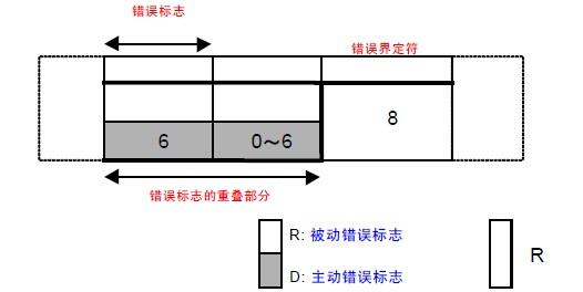
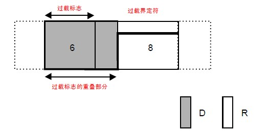
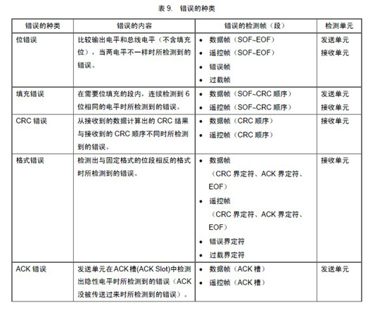
There are a total of5 types of errors. Multiple errors may occur simultaneously.
The types of errors, error contents, error detection frames, and detection units are shown in Table 9 .
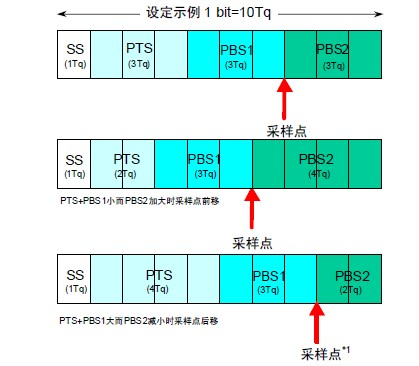
The number of bits sent per second by the sending unit in asynchronous conditions is called the bit rate. A bit can be divided into 4 segments.
● Synchronization Segment (SS)
● Propagation Time Segment (PTS)
● Phase Buffer Segment 1 (PBS1)
● Phase Buffer Segment 2 (PBS2)
These segments are composed of the minimum time unit called Time Quantum (hereinafter referred to asTq).
1 bit is divided into4 segments, each segment is composed of severalTq units, which is called bit timing.
1 bit consists of how manyTq units, how manyTq units each segment consists of, etc., can be arbitrarily set for bit timing. By setting the bit timing, multiple units can sample simultaneously, and sampling points can be set arbitrarily.
The functions of each segment and the number of Tq units are shown in Table11 . The composition of 1 bit is illustrated as shown.
6. Methods to Achieve Synchronization
CAN protocol communication method isNRZ (Non-Return to Zero) method. There are no additional synchronization signals at the beginning or end of each bit. The sending unit starts sending data in synchronization with the bit timing. In addition, the receiving unit synchronizes and receives based on the changes in the levels on the bus. However, the clock frequency error between the sending unit and the receiving unit and the phase delay on the transmission path (cables, drivers, etc.) can cause synchronization deviations. Therefore, the receiving unit adjusts the timing for reception through hardware synchronization or resynchronization methods.
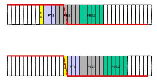
6.1 Hardware Synchronization
The receiving unit performs synchronization adjustments when detecting the start of a frame in the idle state of the bus.
When detecting the edge, the value of SJW is not considered and is regarded as theSS segment. The hardware synchronization process is illustrated as shown.
The hardware synchronization process is illustrated as shown.
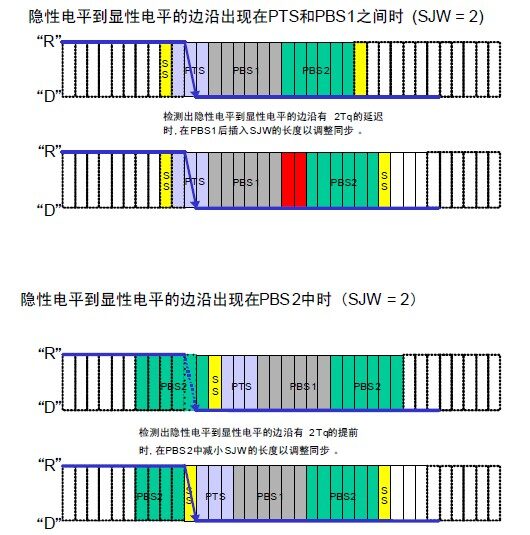
Synchronization adjustments made when detecting changes in levels on the bus during reception.
Each time an edge is detected, the synchronization is adjusted by extending thePBS1 segment or shortening thePBS2 segment according to the SJW value. However, if an error exceeding the SJW value occurs, the maximum adjustment cannot exceed the SJW value.
Resynchronization is illustrated as shown.
6.3 Rules for Synchronization Adjustment
Hardware synchronization and resynchronization follow the following rules:
(1) In one bit, only one synchronization adjustment is performed.
(2) Only when the bus value at the last sampling point and the bus value after the edge are different can that edge be used for synchronization adjustment.
(3) When the bus is idle and there is an edge from the dominant level to the recessive level, hardware synchronization must be performed.
(4) If an edge from the recessive level to the dominant level detected when the bus is not idle meets conditions (1) and (2), resynchronization will be performed. However, the following conditions must also be met.
(5) If the sending unit observes a delay in its own output of the dominant level, resynchronization will not be performed.
(6) In the case where multiple units are sending simultaneously from the start of the frame to the arbitration segment, no resynchronization will be performed on the delayed edge.
Source: Automotive Maintenance and Repair
● Note! Don’t attempt to repair new energy vehicles if you don’t understand, be careful to lose your life.
● CCTV exposes charging pile investment scams, is this “pile” business really good to do?
● How to charge a small battery of new energy vehicles when it runs out of power.
● CCTV exposes charging pile investment scams, is this “pile” business really good to do?