Unveiling Low-Power Embedded Systems: A Comprehensive Implementation from Flowchart to Code
In battery-powered embedded devices, low-power design is crucial for extending battery life. This article takes the “low-power processing system with an independent watchdog” as an example, combining flowcharts and code implementations to dissect the core logic of low-power design, exploring how to enable seamless switching between “active” and “sleep” modes to maximize battery life.
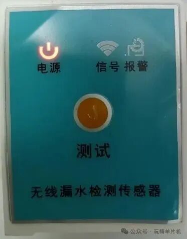
1. Core Objective of Low-Power Design: Dynamic Balance Between Performance and Power Consumption
For small lithium battery-powered devices such as leak detection and portable terminals, it is essential to ensure real-time responsiveness (e.g., leak alarms, button operations) while minimizing standby power consumption. The system achieves this balance through three main strategies:
1. Dynamic mode switching: Distinguishing between “normal operating mode” and “sleep mode”, entering low-power sleep state when not necessary;
2. Precise wake-up control: Triggering wake-up through buttons, timers, etc., allowing the device to “wake when it should, sleep when it should”;
3. Fine management of peripherals: Turning off unnecessary peripheral clocks, keeping only the wake-up related modules running.
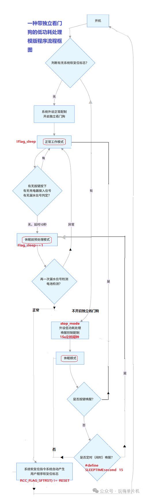
2. Low-Power Operating Logic from Flowchart: A Closed Loop of “Sleep – Wake – Work” Cycle
The entire system process forms a closed loop around “power-on initialization → mode judgment → state detection → sleep / wake-up”, with the core nodes as follows:
1. First step after power-on: Determine reset state to decide initialization path
Key judgment: After the system powers on, it first checks the “system soft reset flag (RCC_FLAG_SFTRST)” to distinguish between the two scenarios of “power-on startup” and “sleep entry”. Why is this necessary? Because once the independent watchdog is enabled, the user program cannot turn it off.
If there is no reset flag (power-on startup): Execute normal peripheral configuration, enable the independent watchdog (to prevent system crashes), and enter “normal operating mode”;
If there is a reset flag (sleep entry): Directly enter low-power related configuration to prepare for sleep.
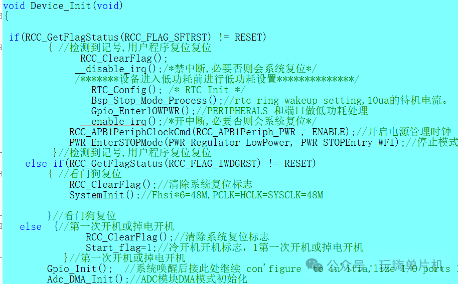
2. Normal operating mode: Run on demand, sleep on timeout
In “normal operating mode”, the system continuously monitors three major events (corresponding to the flowchart “button pressed / charger connected / leak signal”):
If an event is detected (e.g., leak alarm): Maintain working state and execute corresponding processing (e.g., sound and light alarm, data upload);
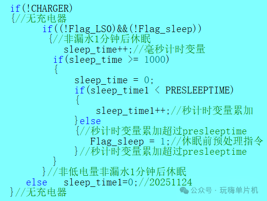
If no events occur within 10 seconds: Trigger “pre-sleep processing”.
void master(void)
{
if(!Flag_sleep)
{ // Normal working state: process sensor data, buttons, wireless transmission, etc.
// … Normal working logic (e.g., leak detection, battery voltage detection, LED indication)
} else { // Pre-sleep processing
WDG_ReloadCounter();// Feed the watchdog (to avoid watchdog reset)
ADC_data();// Last check of sensor status
if(Flag_LS0==1) { // If leak is detected, configure 1ms timer to wake up process Haltmode_PeriphClk_WU2();// Enable working mode timer (1ms timer) and enter normal operating mode
} else if((!Flag_BAT)&&(!Flag_LS0))
{ // No leak and battery normal: deep sleep (reset system to minimize power consumption) BATLOW_SleepTimer=0;
NVIC_SystemReset(); // Reset system to restart without watchdog entering sleep
}
else if((FlagLOWVOL_bat)&&(!Flag_LS0))
{ // No leak but battery low: periodic wake-up check (enter sleep after 300 cycles) if(BATLOW_SleepTimer<300)
{ BATLOW_SleepTimer++;// Count
NVIC_SystemReset(); // Reset system to restart without watchdog entering sleep
} else { // Switch to working mode after 300 cycles
Flag_sleep = 0;
Haltmode_PeriphClk_WU2();//Enable working mode timer (1ms timer)
}
}
}
}
3. Wake-up Mechanism: Precise Response, Quick Recovery
In sleep mode, the system can be awakened in two ways (corresponding to the flowchart “button wake-up” and “timer wake-up”):
Button wake-up: External button triggers an interrupt, immediately exiting STOP mode;
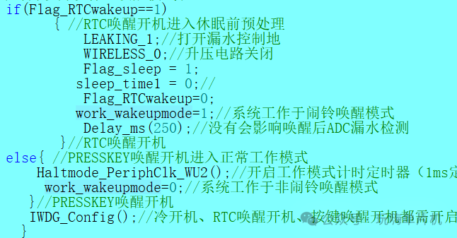
Timer wake-up: RTC alarm triggers after 15 seconds (modifiable via #define SLEEPTIME 15), periodically waking up to check status.
After waking up, the program will set the “related flag bits”, entering normal mode or pre-sleep processing, achieving a “sleep – wake” closed loop.
/* RTC WAKEUP settings before sleep */
void Bsp_Stop_Mode_Process(void)
{
RTC_AlarmConfig();// RTC alarm settings before sleep, RTC wake-up
PWR_ClearFlag(PWR_FLAG_WU);// Must clear this flag, otherwise it will wake up immediately after entering low power
RTC_ClearFlag(RTC_FLAG_ALRAF);
RTC_ClearITPendingBit(RTC_IT_ALRA);
EXTI_ClearITPendingBit(EXTI_Line17);// Must clear this, otherwise it will keep interrupting and crash
}
3. Conclusion
The entire process centers around the core objective of “low power consumption”, distinguishing initialization paths through the “system soft reset flag”, utilizing “buttons, timers, and abnormal signals” as wake-up sources, and combining the independent watchdog to ensure system stability, achieving dynamic switching between “normal operation – sleep”. Practically, almost all products require enabling the independent watchdog; if you see someone trying to avoid enabling it for the sake of convenience in sleep mode (the watchdog will wake up due to timeout), please understand: this is for learning and experimental training; mature embedded developers would not do this!
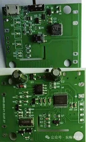
This logic set is not only applicable to leak detection devices but can also be extended to all battery-powered embedded systems. Through collaborative design of hardware and software, making “low power consumption” no longer an abstract concept, but a tangible code process.