In the field of electronic manufacturing, underfill materials play a crucial role in ensuring the reliability of electronic devices. Today, we will delve into the IPC J-STD-030A standard document, providing a comprehensive understanding of the selection and application points for board-level underfill materials.
Underfill Materials: The “Stabilizers” of Electronic Devices
Underfill materials are primarily used to enhance the reliability of electronic devices, possessing two main “treasures”: first, they alleviate the mismatch of the coefficient of thermal expansion (CTE) between electronic packaging and assembly substrates; second, they improve mechanical strength. Additionally, they provide environmental protection, resist mechanical shocks and vibrations, and even serve as tamper-proofing. There are various types of underfill materials available in the market, commonly including capillary flow underfill materials, non-flowing/soldering underfill materials, and removable/reworkable underfill materials, each with its unique characteristics and applicable scenarios.
Design Considerations Before Material Selection
Before selecting underfill materials, design factors must be thoroughly considered. For instance, in footprint design, it is essential to avoid placing passive or other components too close to the device requiring underfill, as this may affect the dispensing operation and potentially lead to material flowing into undesired areas. Additionally, testing points should be positioned away from the outflow area of the underfill material to avoid impacting circuit testing.
The gap size is also critical, referring to the distance between the assembled package and the circuit board. The appropriate size and dimensions of the underfill material should be based on the device’s gap size; generally, the size of the underfill material should be one-third of the minimum gap. Furthermore, when redistributing pads, it is crucial to ensure that the forces acting on the chip are balanced during the reflow process.
Characteristics of Uncured Materials: Key Factors Affecting Usage
- Filler Characteristics: Fillers play an important role in underfill materials, with common fillers including silica and alumina. The type, particle size, distribution, and geometry of the fillers can all affect the material’s performance. For example, the particle size of the filler should be smaller than the effective gap size; otherwise, it will restrict the material’s flow. Additionally, the filler content will also influence the material’s ability to alleviate CTE mismatch.
- Prepolymer Characteristics: The viscosity of the prepolymer affects the material’s flow rate and dispensability, and the viscosity changes over the material’s shelf life. Gel time refers to the time when the liquid begins to exhibit pseudo-elastic characteristics, which can vary depending on the curing system and preheating conditions. During use, care should be taken to avoid reaching the gel point during the filling process.
- Material Compatibility: Material compatibility includes compatibility with flux, circuit board surfaces, and component surfaces. Residual flux may hinder the wetting of the underfill material and may chemically react with the material, affecting its final performance. If the solder mask on the circuit board absorbs moisture or is not fully cured, it can lead to voids and delamination in the underfill material. The component surfaces requiring underfill must have good adhesion to prevent delamination.
- Alpha Particle Emission: Certain levels of alpha particle emission can cause soft errors in memory devices. The fillers in underfill materials are the primary source of alpha particle emission; however, suppliers typically use low-alpha-emission fillers to reduce risk.
Material Packaging, Handling, and Storage: Details Determine Success
- Packaging and Containers: Underfill materials are typically packaged in sealed plastic syringes, with labels indicating important information such as product, batch number, and expiration date. It is essential to select appropriately sized syringes or cartridges to match the material’s usable period and the production unit’s consumption. Additionally, care should be taken to prevent bubbles from forming inside the packaging to avoid material leakage.
- Storage Conditions: Most underfill materials are pre-mixed and frozen two-component epoxy resins that require low-temperature storage. Different materials have varying storage temperature requirements; materials with high filler content typically need to be stored in low-temperature refrigerators to ensure their shelf life and performance.
- Pre-treatment: Underfill materials stored in a frozen state need to be pre-warmed to room temperature before use, and temperature shocks should be avoided to prevent voids from forming inside the syringe.
- Usable Period: The usable period of underfill materials can be assessed through viscosity changes, flow rate changes, and sedimentation tests. If the material’s viscosity increases excessively, the flow rate decreases significantly, or sedimentation of fillers occurs, it indicates that the material may have expired or is nearing expiration and is unsuitable for continued use.
Application Process: Attention to Detail at Every Step
- Preparation of Circuit Boards Before Application: To prevent moisture-related voids in the underfill material during reflow and curing, the circuit board must remain dry. Circuit boards exposed to ambient air for more than four hours require thorough drying treatment.
- Application of Capillary Flow Underfill Materials: When applying capillary flow underfill materials, the device to be filled must first be secured, and then the material is dispensed to the edges of the components using specialized equipment, allowing capillary action to flow the material and fill the gaps. During dispensing, it is important to select appropriate dispensing modes and parameters to avoid air entrapment, phase separation, and other issues.
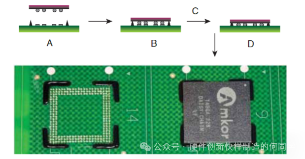
- Application of Non-Flowing/Soldering Underfill Materials: Non-flowing/soldering underfill materials are typically dispensed directly onto the circuit board before component placement, after which the components are placed on the material for reflow. During application, it is crucial to control the dispensing volume and pattern to avoid bubbles and “floating” phenomena.
- Flow Rate: The flow rate of underfill materials includes dispensing flow rate and filling flow rate, both of which are critical for assessing material performance. Specific testing methods can be used to measure flow rates, and appropriate flow rate ranges should be determined based on actual application needs.
- Expansion/Collapse: Expansion/collapse refers to the flow behavior of underfill materials during application; excessive expansion or collapse may affect adjacent devices. Specific testing methods can be used to evaluate the expansion/collapse performance of the material to ensure compliance with requirements.
- Evaluation Methods: To ensure the filling quality of underfill materials, various evaluation methods such as acoustic microscopy and destructive testing can be employed. These methods can detect the integrity of the material filling, as well as any voids and cracks.
- Usable Period (in Dispenser): In the dispenser, the usable period of underfill materials can be assessed through changes in dispensing flow rate. Generally, when the dispensing flow rate decreases by 50%, it is considered that the material’s usable period has expired.
Curing Process: Grasping Key Points to Ensure Quality
- Service Life (Post-Dispensing): Underfill materials should be cured as soon as possible after dispensing and flowing; otherwise, issues such as filler sedimentation and moisture absorption from the atmosphere may occur, affecting curing quality. Before curing, the gel time of the material should be checked to avoid reaching the gel point before complete filling.
- Curing Process of Capillary Flow Underfill Materials: Parameters of the curing process, such as heating rate, cooling rate, maximum temperature, and dwell time, all affect the final curing performance. When selecting curing parameters, it is essential to fully consider the material’s characteristics and the device’s requirements to ensure optimal curing results.
- Curing Process of Non-Flowing Underfill Materials: Non-flowing underfill materials are typically cured in IR or convection surface mount reflow ovens. During the curing process, it is crucial to ensure that solder joints complete reflow before the material gels; otherwise, poor soldering may occur. Additionally, care should be taken to avoid voids in the material during curing, which can be mitigated through pre-drying measures to reduce moisture impact.
- Void Formation/De-gassing: During the curing process, voids may form in the underfill material, potentially due to the presence of solvents, diluents, or moisture. Testing should be conducted to assess the formation of voids, ensuring that the material does not exhibit significant void issues in practical applications.
- Curing Verification: Curing verification can be performed by comparing rounded corners with known cured samples, needle probe hardness testing, and observing color changes. The most accurate method is to use thermal analysis techniques, such as Differential Scanning Calorimetry (DSC) and Thermomechanical Analysis (TMA), to determine the degree of curing and the material’s performance.
Properties of Cured Underfill Materials: Performance Indicators Revealed
- Appearance: The appearance of cured underfill materials includes aspects such as rounded corners and color. Rounded corners can disperse stress and enhance reliability, but they should not cover the top of the package. Most underfill materials are colored for visibility, and care should be taken to consider how color affects material performance.
- Adhesion: The adhesion of underfill materials is critical to their performance and can be assessed using testing methods such as ASTM D1002. However, since the expected field failure is fatigue fracture of the underfill layer, the obtained shear strength values may not accurately predict the material’s behavior in actual use.
- Shrinkage and Induced Stress: Shrinkage and induced stress can affect device performance and can be measured using interferometers and profilometers. Selecting appropriate underfill materials can reduce shrinkage and induced stress, improving device reliability.
- Young’s Modulus: Young’s modulus reflects the stiffness of the material; for CTE-sensitive applications, materials with higher Young’s modulus are typically desired, while for devices like CSP that are susceptible to impact, drop, or vibration stress, lower modulus materials may be required.
- Coefficient of Thermal Expansion (CTE): Traditionally, it is believed that the CTE of underfill materials should match that of the interconnection system, but there is still debate regarding the optimal CTE. Additionally, attention should be paid to changes in CTE above and below the glass transition temperature.
- Glass Transition Temperature (Tg): Tg is typically determined by the maximum final use temperature and/or the highest temperature exposure identified. If the material expands similarly above and below the glass transition region, the impact of Tg is relatively minor.
- Chemical Stability: Underfill materials should exhibit high chemical stability, which can be assessed through solvent immersion testing methods to evaluate solvent resistance. Additionally, the material’s resistance to other potential chemical substances should be tested.
- Moisture Absorption: Moisture absorption of cured underfill materials can affect device performance, and suppliers typically measure moisture absorption rates through 24-hour boiling water immersion tests. Generally, moisture absorption rates should be controlled within a certain range.
- Hydrolytic Stability: Hydrolytic stability refers to the material’s ability to maintain its structure under high temperature and humidity conditions. Although there are currently no specific hydrolytic stability testing standards for underfill materials, relevant general testing methods can be referenced for evaluation.
- Non-Nutritive: To prevent biological growth from damaging devices, underfill materials should be non-nutritive, which can be tested using IPC – TM – 650, TM 2.6.1 testing methods.
- Surface Insulation Resistance: Surface insulation resistance is used to measure the insulation characteristics of materials and can be assessed using IPC – 9201 and other testing methods. During testing, attention should be paid to changes in resistance under humid conditions.
- Electrochemical Migration Resistance: Electrochemical migration resistance is similar to surface insulation resistance testing but requires a longer testing time. It can be evaluated using IPC – TM – 650, TM 2.6.14.1 testing methods.
- Volume Resistivity: Volume resistivity reflects the bulk insulation characteristics of materials and can be measured using ASTM D257 testing methods. The volume resistivity of materials is influenced by factors such as temperature, humidity, and degree of curing.
- Dielectric Constant (Capacitance): The dielectric constant and dissipation factor are inherent properties of polymer materials. For underfill materials used near microwave or other RF signal paths, their dielectric characteristics should be considered. The dielectric constant and dissipation factor can be measured using ASTM D150 testing methods.
Process Reliability Assessment: Multi-Dimensional Considerations to Ensure Quality
- Ion Content: Excessive ion content, such as chloride and sodium ions, can lead to corrosion of pads and printed circuit conductors. Different types of underfill materials have varying limits on ion content, which can be detected through ion chromatography.
- Chemical Resistance: Underfill materials can provide a certain degree of protection for packaging and solder interconnections under harsh environmental conditions, but testing is required to determine their compatibility with expected environmental conditions.
- Mechanical Integrity: Underfill materials provide mechanical connections between the circuit board and packaging, and good adhesion is crucial for enhancing mechanical reliability. Additionally, other physical properties, such as elastic modulus, will also affect the performance of underfill materials.
- Post-Soldering Process (Capillary Underfill): Capillary underfill is typically performed after the soldering/reflow process, during which residual flux may be present on the surface, requiring good compatibility between the underfill material and the flux. In some cases, if the soldering reflow process occurs after the application and curing of the underfill layer, materials that can withstand high temperatures need to be selected.
- Temperature Cycling: Temperature cycling testing is one of the important methods for assessing the reliability of underfill materials. By simulating temperature changes during actual use, the performance changes of the device can be observed. When selecting underfill materials, factors such as CTE and glass transition temperature should be considered to ensure device reliability during temperature cycling.
Other Considerations: Don’t Overlook These Key Points
- Reworkability: When rework costs are reasonable, reworkable underfill materials are a good choice. During the rework process, care should be taken to avoid damaging the circuit board and surrounding devices while ensuring that the performance of the reworked device meets requirements.
- Curing Determination: The best method to determine the curing degree of underfill materials is through DSC analysis. During the curing process, it is essential to fully consider the thermal mass of components, circuit boards, and other items to ensure that the material reaches the required time and temperature for complete curing.
- Thermal Management: Although thermally conductive underfill materials can be used for heat dissipation, since solder joints are effective heat conduction pathways, underfill materials are typically not used specifically for thermal management. Heat sinks are a more commonly used thermal management method.
- Process Standards for BGA and CSP Board-Level Underfill Materials: For BGA and CSP board-level underfill materials, detailed process standards exist, including visual standards and acceptable levels of underfill voids. During production, strict adherence to these standards is required for inspection and control.
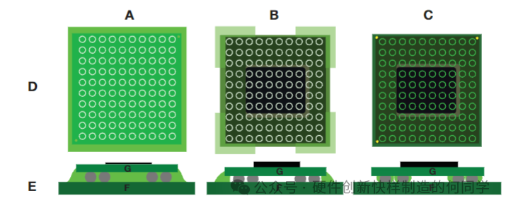
- Destructive Testing: Destructive testing can be used to observe the flow and coverage of underfill materials and to detect any voids or defects. By inspecting exposed solder pad arrays, the quality of the underfill material can be assessed.
- Void Conditions and Reliability Impact/Factors Overview: Different types of voids have varying impacts on device reliability, requiring specific assessments based on the situation. If uncured material is found, reliability testing should be conducted to determine whether it should be considered a defect.
- Process Guidelines for Corner or Edge Bonding Underfill Materials: For corner or edge bonding underfill materials, clear process guidelines exist, such as requirements for adhesive length, fill height, fill width, and adhesive shape. Adhering to these guidelines can enhance device reliability.
Troubleshooting Common Issues: Clever Solutions to Problems
- Insufficient Flow: Insufficient flow may be caused by viscosity, wettability, or mechanical blockage. Solutions include measuring viscosity, checking for surface contamination, and eliminating mechanical blockage factors.
- Phase Separation: Phase separation may occur due to blockage or the inherent properties of the material. For low-viscosity systems, phase separation may be more likely to occur, which can be resolved by selecting appropriate materials or adjusting processes.
- Voids: Voids may appear before and after curing, caused by air entrapment, bubbles in the material, or moisture evaporation. Solutions include optimizing flow patterns, checking material packaging, and pre-drying components to reduce void formation.
- Insufficient Curing: Insufficient curing is typically due to inadequate temperature and/or time, which can be resolved by inserting thermocouples to test actual temperatures, optimizing curing conditions, or assessing material compatibility.
- Poor Adhesion: Poor adhesion may result from contaminants, moisture, or unsuitable materials. Solutions include cleaning surfaces, pre-baking, selecting appropriate materials, or increasing curing temperatures to improve adhesion.
- Thermal Cycling Failure: Thermal cycling failure may be caused by various factors, such as poor adhesion, moisture, voids, or inappropriate modulus. Failure analysis and material characterization can help identify specific causes and implement corresponding measures.
Underfill materials are crucial in electronic manufacturing. From material selection to application, curing, and subsequent evaluation and troubleshooting, every step requires strict control. We hope this article helps everyone better understand and apply underfill materials to enhance the reliability of electronic devices. If you have any other questions in practical operations, feel free to share and discuss in the comments section!