This article aims to provide you with an intuitive understanding of Modbus, summarizing knowledge related to Modbus, making it very suitable for beginners. If there are any errors, suggestions and corrections are welcome.
What is a Protocol
Before understanding what Modbus is, let’s first look at what a protocol is.
A protocol is a Chinese term pronounced as xié yì, meaning a common agreement or negotiation; a document that is mutually recognized and adhered to after negotiation and consultation.
In simple terms, when our microcontrollers communicate with each other, as well as between microcontrollers and host computers, different content specifications are defined, which both parties in the communication need to adhere to, thus enabling communication between them.
This protocol specification can take many forms to accommodate different devices and communication requirements. Common examples include IIC, SPI, and UART serial communication protocols, among others. Modbus is also a serial communication protocol.

What are RS-485 and RS-232
When looking at Modbus, we often see 485 and 232 serial ports. What are these?
RS232 and RS485 are types of voltage standards.
Data is transmitted between the two parties in communication, essentially transmitting physical voltage levels, for example, transmitting a 5V signal and a -1V signal. These physical signals can be affected by various interferences during transmission. For instance, a 5V signal may arrive at the receiving end as 4.8V, and the reference voltage for high and low levels may differ between the two parties.
At this point, a voltage standard is needed to determine what voltage level corresponds to a high level (1) and what voltage level corresponds to a low level (0). This is where RS-485 and RS-232 come into play.
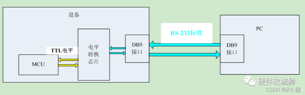
RS232: This is an asynchronous transmission standard interface established by the Electronic Industries Association (EIA), which corresponds to voltage standards and communication protocols (timing). Its voltage standard is: +3V to +15V corresponds to 0, -3V to -15V corresponds to 1.
Full duplex
Logic 1: -15V to -5V
Logic 0: +3V to +15V
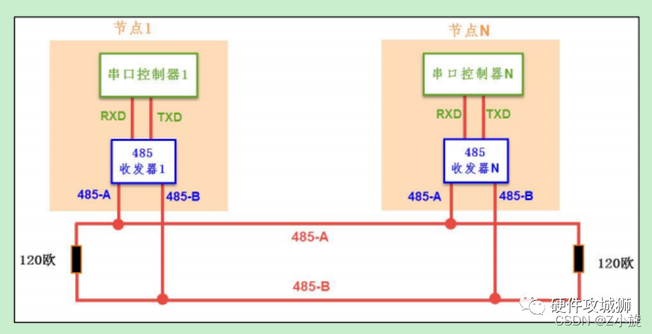
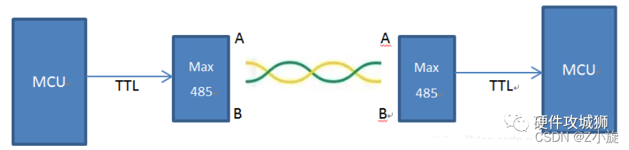
RS485: RS485 is a serial interface standard that uses differential signaling for long-distance transmission, which is much more resistant to interference than RS232. A differential voltage of -2 to -6V represents 0, while a differential voltage of +2 to +6V represents 1.
Half duplex
Logic 1: +2V to +6V
Logic 0: -2V to -6V
Note that the voltage levels for 485 refer to the two transmission lines, 485-A and 485-B, and the voltage difference between them, not the voltage on the transmission lines.
If you want to learn more, you can check out the author’s blog post:
Differences between USB to Serial TTL RS-232 RS-485 COM Port UART
In other words, the RS-485 voltage standard determines whether the transmitted data is 0 or 1. Based on this, these byte data are exchanged according to the Modbus communication protocol.
Hardware layer protocol: Ensures reliable transmission of 0s and 1s, commonly includes RS232, RS485, CAN, IIC, SPI, etc.
Software layer protocol: Addresses transmission purposes, commonly includes Modbus, TCP/IP, CANopen, etc.
Modbus Protocol Description
Modbus was born in 1979 at Modicon and was later acquired by Schneider Electric. Modbus provides a common language for devices to communicate with each other.
Modbus has become the industry standard for communication protocols in the industrial field and is now a commonly used connection method between industrial electronic devices. As the most widely used protocol in the industrial field,
In simple terms, Modbus is a bus communication protocol, similar to IIC and SPI, but it does not rely on a hardware bus.
The widespread use of Modbus is due to its advantages.
The Modbus protocol standard is open, publicly published, and has no copyright requirements.
The Modbus protocol supports various electrical interfaces, including RS232, RS485, TCP/IP, and can also be transmitted over various media such as twisted pair, fiber optics, infrared, and wireless.
The Modbus protocol message frame format is simple, compact, and easy to understand. Users find it easy to comprehend and use, manufacturers can easily develop and integrate it, facilitating the formation of industrial control networks.
For example, the commonly used IIC communication protocol requires a physical connection to the IIC bus, along with pull-up resistors, and specifies the high and low levels of the physical layer.
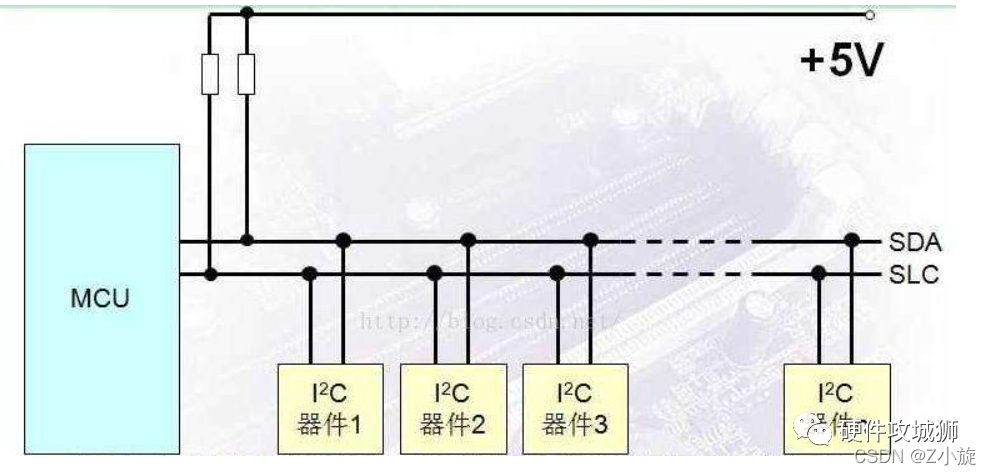
In contrast, the Modbus protocol is an application layer message transmission protocol that does not define the physical layer but defines the message structure that controllers can recognize and use, regardless of the network used for communication. Therefore, it can adapt to various electrical interfaces, making it widely used.
Modbus Communication Process
Note that Modbus is a master-slave communication protocol.
In Modbus communication, only one device can send requests. Other slave devices receive data sent by the master and respond. Slaves can be any peripheral devices, such as I/O sensors, valves, network drives, or other types of measuring devices. The slave processes the information and uses Modbus to send its data to the master.
This means that Modbus cannot perform synchronous communication; the master can only send requests to one slave at a time. Only one piece of data can be transmitted on the bus at a time, meaning the master sends, the slave responds, and when the master does not send, there is no data communication on the bus.
Slaves do not send messages to the master on their own; they can only respond to messages sent by the master.
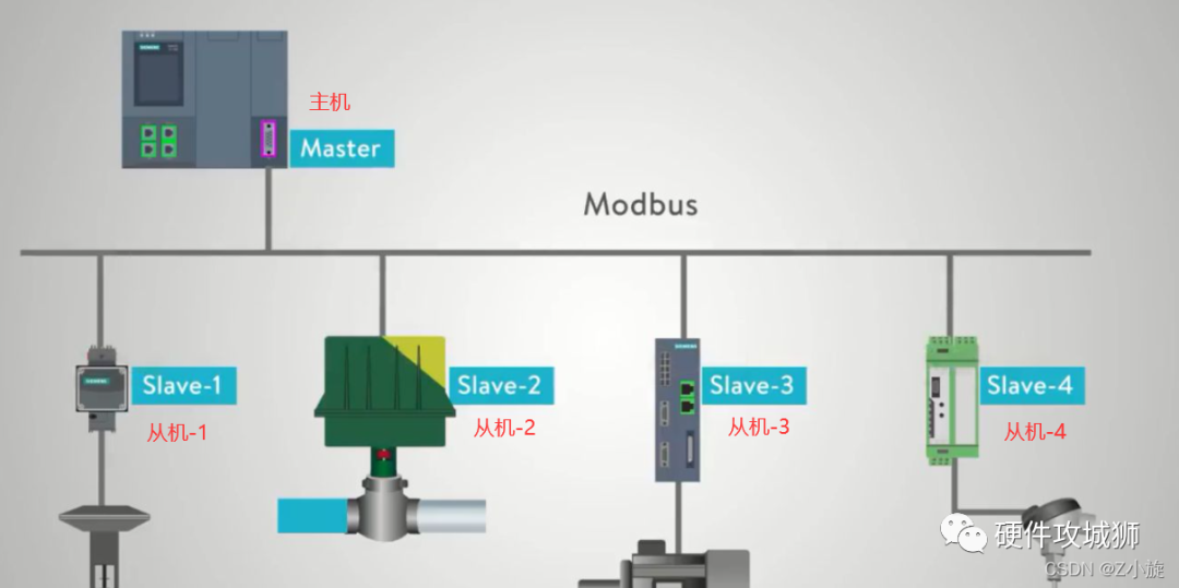
Moreover, Modbus does not have a busy mechanism to determine if the slave has received the command from the master or is processing something else. In this case, it cannot respond to the master because the Modbus bus only transmits data without any other arbitration mechanism. Therefore, software methods are needed to determine whether the reception is normal.
Example
Now, let’s explore the way Modbus data transmission works, which can be simply understood as making a phone call. It is a one-way communication phone call.
The master sends data, first needing the slave’s phone number (distinguishing each slave, each address must be unique), telling the slave what to do, followed by the content to be sent, and finally asking the slave if it understood everything correctly.
Then, the slave receives the master’s call and replies with the required content, and the master receives the slave’s data. This is the communication process from master to slave.
It’s like a teacher calling you; the teacher dials your number and says, “Xiao Wang, I need you to send me something, the content is the weekly summary from last week.” You say okay, then open your computer’s folder and send your weekly report to the teacher. This is a communication process.
Modbus Storage Areas
Since slaves store data, there must be a storage area, which requires file operations. We know that files can be divided into read-only (-r) and read-write (-wr) types.
Moreover, the stored data types can be divided into: Boolean values and 16-bit registers.
Boolean values include the high and low levels of IO ports, the on/off status of lights, etc.
16-bit registers include sensor temperature data, stored passwords, etc.
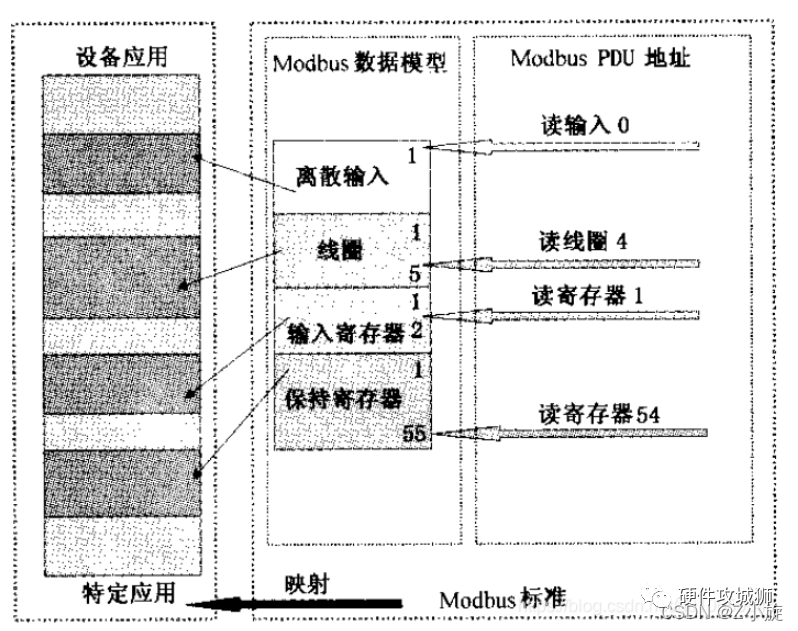
The Modbus protocol defines four storage areas: 0, 1, 3, and 4, where areas 1 and 4 are read-write, and areas 1 and 3 are read-only.

Additionally, Modbus assigns an address range to each area. When the master retrieves data from the slave, it only needs to tell the slave the starting address of the data and how many bytes of data to retrieve, and the slave can send data back to the master.
The Modbus data model specifies the exact address range. Each slave has actual physical storage corresponding to the Modbus storage areas, and when the master reads and writes to the slave’s storage areas, it is essentially reading and writing to the actual storage space corresponding to the slave device.
Types of Modbus Protocol
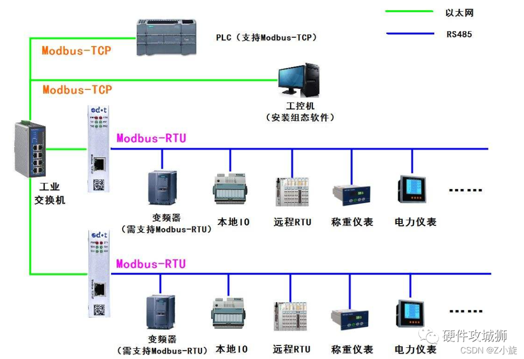
As we have explained, Modbus can be transmitted over various media, and its transmission modes are divided into three types: ASCII, RTU (Remote Terminal Unit), and TCP.
There are multiple versions of the Modbus protocol for serial ports, with the most common being the following four:
Modbus-RTU
Modbus-ASCII
Modbus-TCP
ModbusPlus
Modbus RTU is a compact way of representing data in hexadecimal, while Modbus ASCII represents data using ASCII code, with each 8-bit byte sent as two ASCII characters.
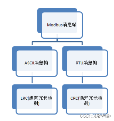
The RTU format includes a cyclic redundancy check (CRC) checksum for subsequent commands/data, while the ASCII format uses longitudinal redundancy check (LRC) for checksums.
When using the Modbus protocol over serial transmission, one can choose between RTU or ASCII modes, which specify the message, data structure, commands, and response methods, and require data checks. The ASCII mode uses LRC checks, while the RTU mode uses 16-bit CRC checks. When transmitted over Ethernet, TCP is used, which does not require checks since the TCP protocol is a connection-oriented reliable protocol.
Of course, the commonly used mode is RTU, while ASCII is rarely used.
For example, if we need to send the number 10, in RTU mode, we only need to send 0x0A, and the data transmitted on the bus is: 0000 1010.
In ASCII mode, the data 1 and 0 are converted to ‘1’ and ‘0’, requiring sending 0x31 (1) and 0x30 (0) as two bytes of data. The data transmitted on the bus is: 0011 0001 0011 0000.
We will elaborate on this later.
Modbus-RTU Protocol
Modbus message frame structure
A message is a frame of data, and a data frame is a message: it refers to a complete string of command data, essentially a string of data.
A Modbus message refers to a frame of data sent from the master to the slave, which contains the slave’s address, the operation the master wants to perform, the checksum, and other content.
The Modbus protocol message format on a serial link is as follows:


Slave Address: Each slave has a unique address, occupying one byte, with a range of 0-255, where the valid range is 1-247, and 255 is the broadcast address (broadcast means sending a response to all slaves).
Function Code: Occupies one byte, the function code indicates what the instruction is for. For example, you can query data from the slave or modify data in the slave, so different function codes correspond to different functions.
Data: Depending on the function code, there are different functions. For example, if the function code is to query data from the slave, this includes the address of the data to be queried and the number of bytes to query.
Checksum: During data transmission, errors may occur, and the CRC check detects whether the received data is correct.
Modbus Function Codes
Modbus specifies multiple functions, and to facilitate the use of these functions, we assign a function code to each function.
The Modbus protocol specifies over twenty function codes, but only eight are commonly used for reading and writing to storage areas, as shown in the table below:

Of course, the most commonly used are 03 and 06, one for reading data and the other for modifying data.
CRC Check
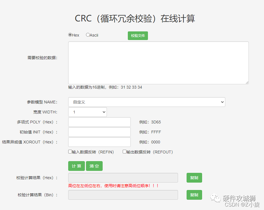
The error check (CRC) field occupies two bytes and contains a 16-bit binary value. The CRC value is calculated by the transmitting device and then appended to the data frame. The receiving device recalculates the CRC value upon receiving the data and compares it with the value in the received CRC field. If these two values are not equal, an error has occurred.
For example, if the master sends 01 06 00 01 00 17 98 04, the last two bytes 98 04 are the checksum. When the slave receives it, it calculates the CRC checksum based on 01 06 00 01 00 17 and checks if its calculated CRC matches the received CRC (98 04 from the master). If they do not match, it indicates that there was an error in data transmission, and this data should be discarded.
CRC Check Process:
1. Pre-set a 16-bit register to 0FFFFH (all 1s), called the CRC register.
2. XOR the first byte’s 8 bits in the data frame with the low byte of the CRC register, and store the result back in the CRC register.
3. Shift the CRC register right by one bit, filling the highest bit with 0, and shifting out the lowest bit for detection.
4. If the lowest bit is 0: repeat step three (next shift); if the lowest bit is 1: XOR the CRC register with a preset fixed value (0A001H).
5. Repeat steps three and four until eight shifts are completed. This processes one complete byte.
6. Repeat steps 2 to 5 for the next byte until all bytes are processed.
7. The final value of the CRC register is the CRC value.
Additionally, there is a method of calculating CRC using a preset table, which is characterized by fast computation speed but requires a large storage space for the table. This method will not be elaborated here.
Next, let’s look at the detailed sending and receiving of data:
1. Master reading data from slave
The master sends the message format as follows:

Meaning:
0x01: Slave address
0x03: Query function, read data from the slave register
0x00 0x01: Represents the starting register address to read, indicating to start reading from 0x0001.
0x00 0x01: The number of registers to query is 0x0001. Modbus stores data in registers, and different variable values are obtained by querying registers. One register address corresponds to 2 bytes of data; the register address corresponds to the actual storage address of the slave.
0xD5 0xCA: Cyclic Redundancy Check (CRC)
The slave replies with the message format as follows:

Meaning:
0x01: Slave address
0x03: Query function, read data from the slave register
0x02: The number of returned bytes is 2, one register is 2 bytes
0x00 0x17: The value of the register is 0017
0xF8 0x4A: Cyclic Redundancy Check (CRC)
2. Master writing data to slave
The master sends the message format as follows:

Meaning:
0x01: Slave address
0x06: Modify function, modify data in the slave register
0x00 0x01: Represents the starting register address to modify, indicating to modify the storage content from 0x0001 to 0x0003.
0x00 0x17: The data value to be modified is 0017
0x98 0x04: Cyclic Redundancy Check (CRC)
The slave replies with the message format as follows:

Meaning:
0x01: Slave address
0x06: Modify function, modify data in the slave register
0x00 0x01: Represents the starting register address to modify, indicating it is 0x0000.
0x00 0x17: The modified value is 0017
0x98 0x04: Cyclic Redundancy Check (CRC)
The slave’s reply and the master’s sending are the same; if they differ, it indicates an error.
Modbus-ASCII Protocol
In this protocol, each byte in the message is sent as two ASCII characters.
The hexadecimal values 0-F correspond to ASCII characters 0-9 and A-F.
That is, 0x30 to 0x3A and 0x41 to 0x46.
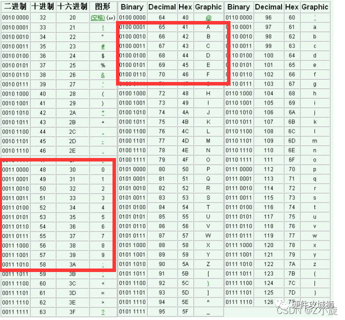
Below is the ASCII message frame:
1 start bit
2 address bits
2 function bits
n data bits, with the least significant bit sent first
LRC (Longitudinal Redundancy Check) Note that the check method is different
End character: \r \n

As you can see, the data portion is more cumbersome. Normally, we use RTU format; the ASCII format is just for understanding.
Conclusion:
Modbus ASCII has a start character (and end character (CR LF)), which can serve as a marker for the beginning and end of a frame of data, while Modbus RTU does not have such markers and requires a time interval to determine the start and end of a message frame. The protocol specifies a time of 3.5 character periods, meaning that before a message frame starts, there must be a period of inactivity greater than 3.5 character periods, and after a message frame ends, there must also be a period of inactivity of 3.5 character periods; otherwise, a packet collision may occur.
Note: The 3.5 character periods refer to a specific time, but this time is related to the baud rate.
In serial communication, 1 character includes 1 start bit, 8 data bits (in general), 1 parity bit (or none), and 1 stop bit (in general), so 1 character includes 11 bits. Therefore, 3.5 characters equal 38.5 bits. The baud rate indicates the number of binary bits transmitted per second, so if the baud rate is 9600, 3.5 character periods = 9600/38.5 = 0.00401s * 1000 = 4.01ms.
Modbus-TCP Protocol
First, let’s look at the differences between Modbus-TCP and Modbus-ASCII.
Modbus-TCP does not require a slave address but needs an MBAP header.
Additionally, it does not require error checking since TCP itself has error-checking capabilities.
The MBAP header format is as follows:
Where the transaction processing indicates the protocol identifier, which we normally set to 0, and the length is 6 bytes, 0x0006.
In simple terms, Modbus-TCP is based on Modbus-ASCII, removing the checks and adding five bytes of 0 and a 06.
Finally, here is the link to the Modbus standard protocol manual:
Modbus Standard Protocol Manual
————————————————
Copyright Statement: This article is an original work by CSDN blogger “Z Xiao Xuan”, following the CC 4.0 BY-SA copyright agreement. Please include the original source link and this statement when reprinting.
Original link: https://blog.csdn.net/as480133937/article/details/123197782
——End——
“If useful, please share”
Copyright Statement: The article is reproduced from the internet, and the copyright belongs to the original author. If there is any infringement, please contact us for deletion!
Click below“Hardware Engineer”to follow; electronic technology dry goods delivered on time!
👇

-
Hand-tear Boost! Boost formula derivation and verification
-
A small sampling resistor has great significance!
-
What is the purpose of a small resistor in the signal line?
-
After reading this, you will also be a PID tuning expert!
-
A mosquito swatter actually has so many circuits; have you learned it all?
-
Let me help you understand every parameter of MOSFET, which will benefit you greatly
-
A very classic voltage power-off monitoring circuit from a big company; have you learned it?
Please like, watch, and share; good articles need your support and encouragement