Hello everyone! Recently, a friend asked me why the Modbus communication between the PLC and the inverter was not working despite following numerous tutorials. I remember when I first started, I was just as confused, struggling with the wiring diagrams and making several mistakes in parameter settings before finally succeeding. Today, I will share the pitfalls I encountered and the steps I summarized, so you can follow along and easily get it done!
📌 Step 1: Prepare the Required Equipment
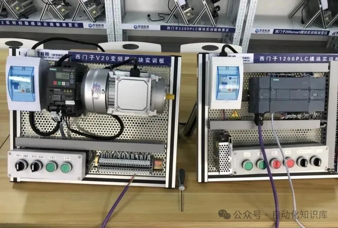
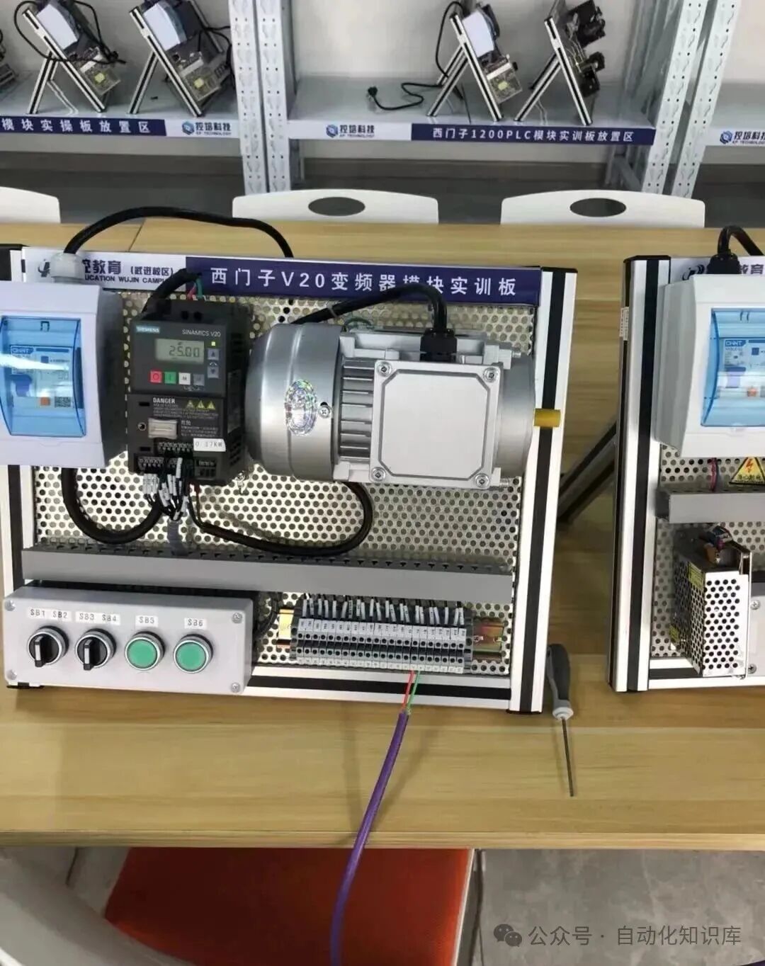
To establish communication, we first need the “main character”—a S7-1200 PLC with an RS485 communication module, and a V20 inverter. I specifically checked the PLC module to confirm it supports RS485, and I chose the commonly used V20 model for the inverter, as this combination is classic, well-documented, and less prone to issues for beginners. If you have the same models, our subsequent steps will align perfectly!
🔌 Step 2: Wire the Devices—Be Careful!
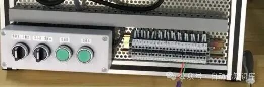
With the equipment ready, it’s time to “connect” them—the wiring of the RS485 module and the V20 inverter. I remember when I first wired it, I was afraid of making a mistake and burning the module, so I specifically chose two wires that were easy to distinguish: the red wire connects to P+, and the green wire connects to N-. You can also use different colored wires to correspond to the terminals, and double-check after wiring to ensure nothing is reversed or loose. After all, wiring is fundamental; if this step is wrong, no adjustments will help!
⚙️ Step 3: Set Parameters for the V20 Inverter
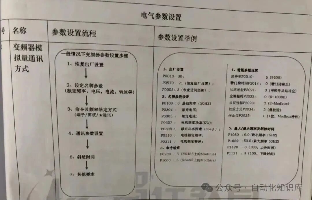
With the wiring complete, it’s time to “set the rules” for the inverter—configure the parameters. Don’t panic; just follow the manual. I referred to the V20 parameter manual and found the communication-related parameters step by step, such as baud rate and data bits (we will match the specific parameter values with the PLC later). When setting, I noted down each parameter I changed to avoid forgetting what I modified; you can develop this habit to facilitate troubleshooting later.
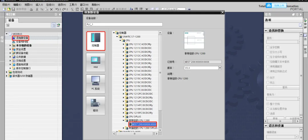
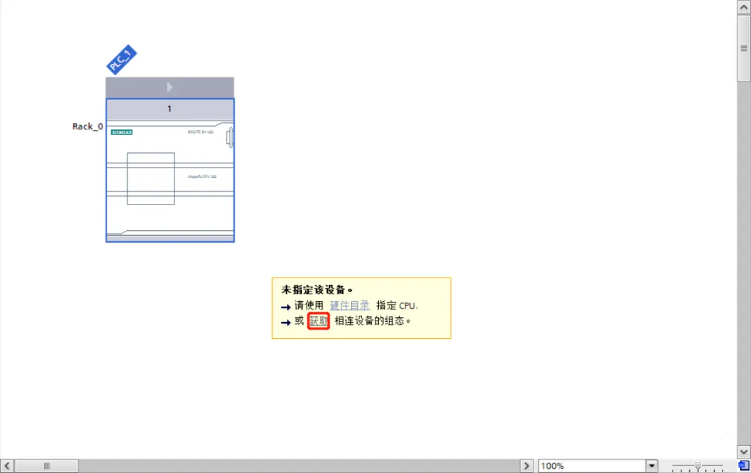
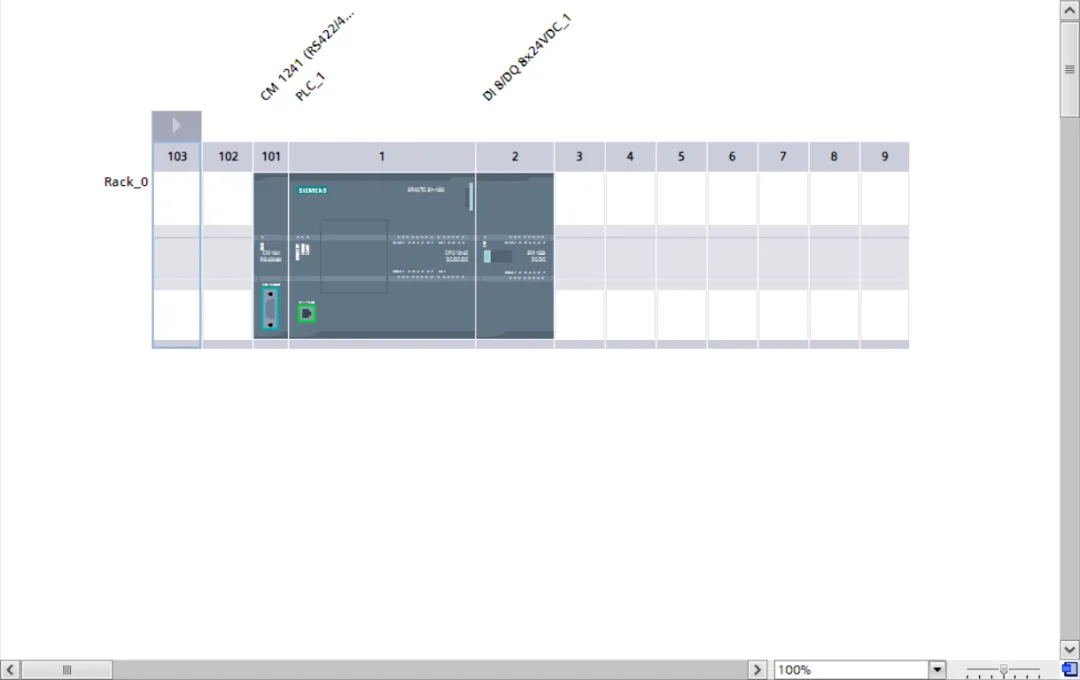
🖥️ Step 4: Create a TIA Portal Project and Set Up the PLC
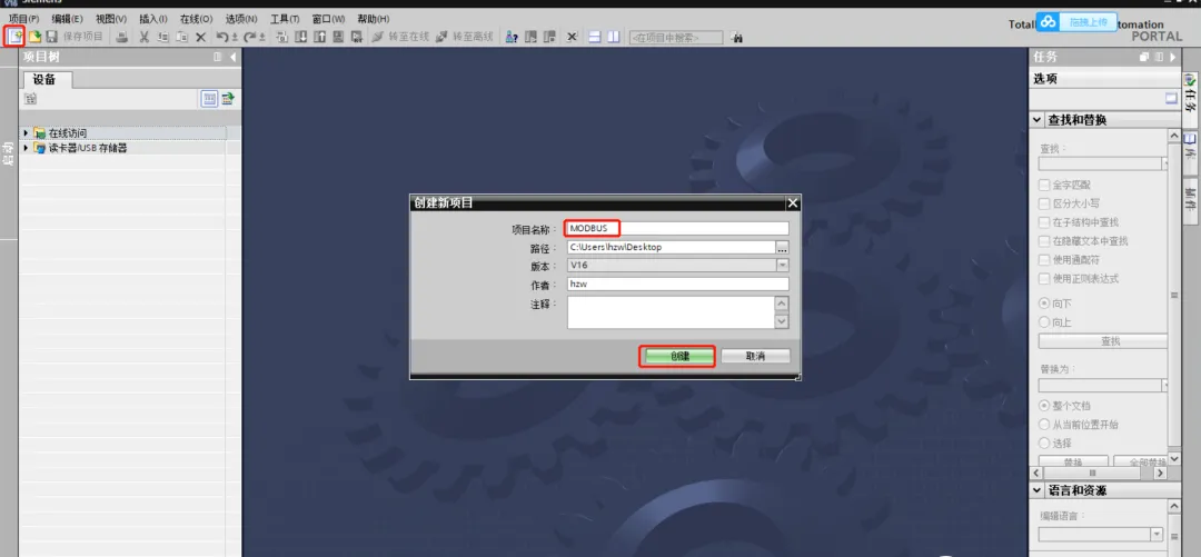
With the inverter parameters set, it’s time for the PLC. We need to create a new project using TIA Portal software and upload the hardware configuration for the S7-1200 PLC. After opening TIA Portal, I created a new project and named it “PLC-V20-Modbus Communication,” then added the corresponding S7-1200 PLC model and the RS485 module to the hardware configuration. When uploading, ensure the PLC is properly connected to the computer; I used a direct Ethernet connection. After a successful upload, the hardware configuration displayed the PLC and module information, which gave me confidence!
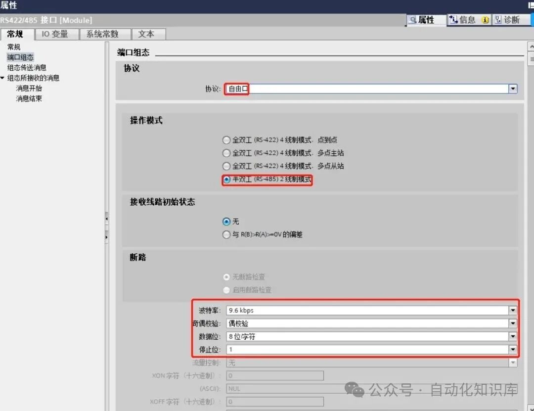
📊 Step 5: Synchronize RS485 Module Parameters to Align with the Inverter
With the hardware configuration set up, the next step is to set the parameters for the RS485 module—it’s crucial that the communication parameters are exactly the same as those of the V20 inverter! I set the baud rate to 9600, data bits to 8, and even parity in the inverter, so I made sure to set the same in TIA Portal: 9600 (baud rate), 8 (data bits), and even (parity). It’s essential that the parameters on both sides “match up”; it’s like two people speaking the same language; otherwise, communication won’t work. After setting, I double-checked twice to confirm I hadn’t made any mistakes.
📥 Step 6: Add Modbus Communication Instructions to Equip the PLC
With the parameters aligned, it’s time to “equip the PLC with a communication tool”—add Modbus communication instructions. In the instruction library of TIA Portal under “Communication,” you can find the Modbus RTU-related instructions. I dragged the initialization, send, and receive instructions into the program. This step is not difficult; it’s like installing software on a computer—just find the corresponding instructions and add them, making it easy for beginners!
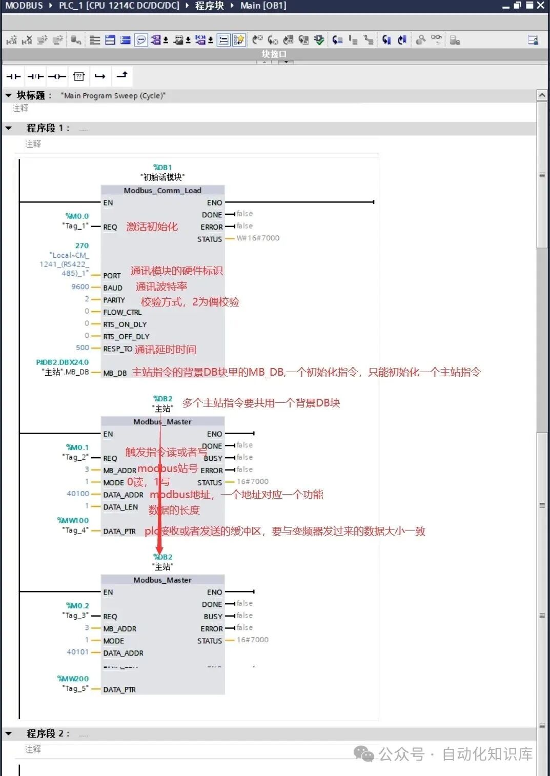
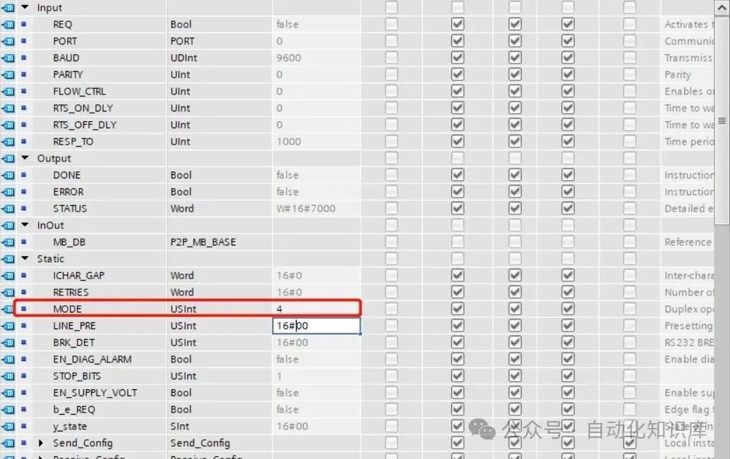
✏️ Step 7: Modify the Mode Parameter of the Initialization Instruction to 4
After adding the instructions, there’s a small detail to change—the mode parameter in the background DB of the initialization instruction should be set to 4. When I looked for this parameter, I double-clicked the initialization instruction to open its background data block (DB block) and found the “mode” item, then manually changed it to 4. This parameter specifies the communication mode, and setting it to 4 is common for communication between PLCs and inverters, so just follow this change!
🚀 Step 8: Program Testing! Check if the Motor Operates Normally
With all the previous steps completed, we finally reach the crucial testing phase—getting the motor to start and stop normally! Here, remember two important Modbus addresses:
- Command Source Address (40100): Used to control the motor’s start, stop, and direction. When I tested, sending “047E” to 40100 stopped the motor; sending “047F” made the motor rotate forward; and sending “0C7F” reversed the motor, which was very responsive!
- Frequency Source Address (also 40100, but note that this is different from the command source): Used to adjust the motor speed. The value range is 16#0 to 16#4000, corresponding to frequencies from 0Hz to 50Hz. For example, if I want the motor to run at 30Hz, I set the value to 16#2666 (since 50Hz corresponds to 16#4000, 30Hz is 60% of 50Hz, so 16#4000×0.6=16#2666). After setting, the motor speed stabilized at 30Hz, which was quite magical!
When you test, start with simple commands to confirm the motor operates normally, then gradually adjust the frequency, taking it step by step—don’t rush!
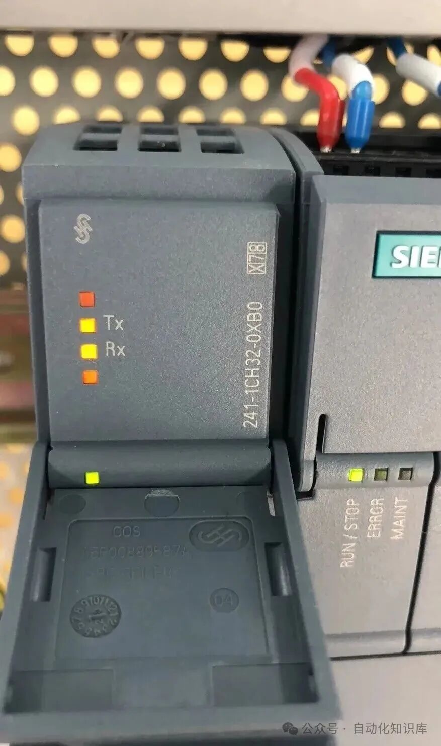
✅ Step 9: Check the Indicator Lights to Determine Communication Success
Finally, we can quickly determine if the communication was successful by observing the indicator lights on the RS485 module. I watched the TX and RX lights on the module, and when I saw them flashing alternately, it indicated successful communication! If the lights are off or only one is lit, it might be due to loose wiring or misaligned parameters; you can go back and check the previous steps to likely find the issue. During my first test, the RX light was off, and I later found it was due to loose wiring; after reconnecting, the light flashed normally, which was very satisfying!
💡 Final Thoughts
In fact, while the steps for Modbus communication between the PLC and inverter may seem numerous, as long as you follow the steps carefully, even beginners can manage it. I also went from being clueless to proficient, having stumbled through wiring and parameter errors, but after several attempts, I grasped the patterns. If you encounter issues during the process, feel free to leave a comment, and we can discuss solutions together. I hope this tutorial helps you, and I wish you success in your first debugging!
Previous Recommendations
In the electrical assembly industry, don’t overlook these process details!
Attention electricians with certification! The difficulty of future reviews will increase.
9 classic PLC programming cases that electrical professionals can easily understand! I have practical experience and included detailed steps.
Advanced electrician interview question “Who gets electrocuted first”? I was confused by the four answers; which one do you think is correct?
Electrician master teaches: Understand electrical symbols, and you’ll never be confused by circuit diagrams again!
Upgrade your home electric kettle with PLC! A step-by-step guide to making temperature control.
Using S7-1200 for dynamic weighing, I broke down the actual engineering case into steps that beginners can understand.
A must-read for electrical professionals! A step-by-step guide to converting electrical diagrams into PLC ladder diagrams.
A must-read for electricians! Two motor nameplates contain key information; an experienced colleague explains how to avoid detours.
Step-by-step guide! Communicating between Kunlun Tongtai MCGS touch screen and Siemens V20 inverter.
From 6k to 300k! 8 career paths for automation professionals, including salary tables and job analysis (insiders choose this way).
Illustrated examples of complete electrical cabinet installations worth saving!
Three minutes to master complex switch cabinets, even beginners can understand!
Advanced engineers use these little tricks: HMI multiplexing variables, easy for beginners to grasp!
Practical sharing: Three modes of controlling a material handling cart with FX3U.
Mitsubishi PLC on-site conveyor control case, a step-by-step guide to understanding!
Step-by-step guide: Displaying PLC time on HMI.
Can you control servos without PLC? A ten-year veteran teaches you how to use Wecon touch screens for Modbus communication!
EPLAN 2.9 software installation tutorial is here—includes download link.
Having trouble with S7-1200 and SMART S7 communication? Don’t worry! A comprehensive, beginner-friendly tutorial is available!
 Share
Share Bookmark
 View
View LikeFollowSo you can find me next time