Analog and Digital Signals
In the process of industrial production control, it is often required to control some physical quantities such as temperature, pressure, flow, etc. These physical quantities change continuously over time, and any value during this continuous change is a specific and meaningful physical quantity. These physical quantities that change continuously over time are referred to as analog signals.
The following figure shows the voltage analog signal changing over time, with voltage fluctuations between -0.2V and 0.3V within the time range of 0~300ms.
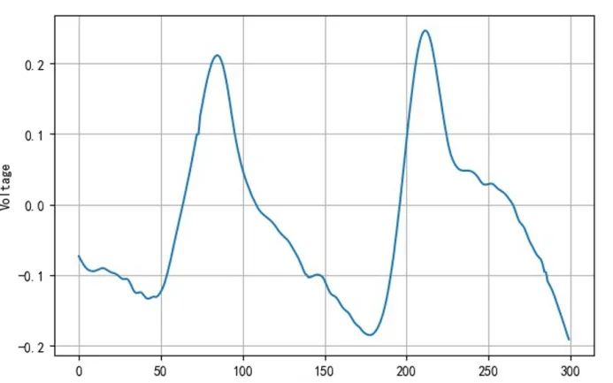
The analog signals collected by sensors need to be input into a computer for storage and processing. However, computers store data in binary numbers, using 8-bit, 16-bit, 32-bit, 64-bit, etc., to represent a value. The number of binary bits can vary; more bits indicate higher precision of the value, while fewer bits indicate lower precision.
For example, using a 16-bit binary number to store a voltage range of -0.2~0.3V, although there are 16 binary bits, the highest bit is the sign bit, so only 15 bits are available to store all real numbers within the range of -0.2~0.3V. With 15 bits, there can be a maximum of 32768 combinations. Therefore, it is necessary to divide -0.2~0.3 into 32768 equal parts, with each part represented by a 15-bit binary number. In this case, any two adjacent parts cannot represent the analog signal, and only by increasing the divisions, which means increasing the number of binary bits, can the representation be achieved.
Therefore, the binary numbers stored in the computer can only approximately represent the analog signals, and this binary number is also referred to as digital signals. Since the sensors output analog signals and microcontrollers can only process digital signals, a Analog-to-Digital Converter (ADC) is typically required at the front end when the microcontroller collects or processes the sensor’s output analog signals. If the microcontroller needs to output an analog signal, it must convert the digital signal back to an analog signal through a Digital-to-Analog Converter (DAC) before outputting it to external devices.
The input of the ADC is an analog signal, and the output is a digital signal. The ADC internally generates a sampling signal to sample the input analog signal at a certain frequency and then converts the sampled values into digital signals.
The sampling signal is a continuous pulse with a certain frequency, and the frequency of the sampling signal is called the sampling frequency, while the frequency of the input signal is called the input frequency. The following figure describes the basic sampling process:
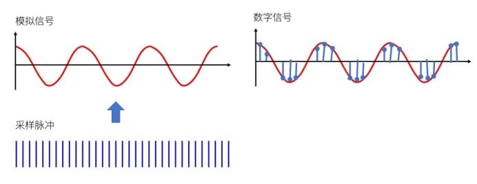
The analog signal is the input signal continuously fed into the ADC. The sampling pulse is generated by the ADC, which retains the instantaneous voltage value of the analog signal through hardware circuits. The ADC converts the retained instantaneous voltage value of the analog signal into a digital signal and encodes it to provide the conversion result before starting the next sampling.
For sampling analog signals, the first step is to determine the sampling frequency, which is the frequency of the sampling pulse. Generally speaking, the higher the sampling frequency, the more sampling points there are, and the more closely the collected digital signal resembles the original analog signal. However, a very high sampling frequency requires a high system processing speed and imposes higher demands on hardware. When the sampling frequency is too low, the collected digital signal is insufficient to reflect the waveform characteristics of the original analog signal, making it impossible to restore the signal.
The rules for determining the sampling signal frequency are as follows: the sampling frequency should be twice the maximum frequency of the original analog signal to ensure that the collected digital signal can adequately restore the original analog signal.
The process of converting the instantaneous value of the original analog signal into a digital signal is called quantization. Since digital signals cannot completely represent analog signals, quantization introduces quantization error. When dividing the analog signal into different quantization levels, different division methods can yield different quantization errors.
Assuming we need to convert an analog voltage signal of 0~1V into a digital signal represented by 3 binary bits, there are only 8 combinations for 3 binary bits. We divide 0~1V into 8 quantization levels, with each level interval being 1/8V. 1/8V is the quantization unit Δ, and each quantization level is a multiple of the quantization unit. For example: 0~1/8V is one quantization level, and the analog voltage within this level is represented by binary 000; 1/8~2/8V is another quantization level, represented by binary 001, and so on. In this division, the quantization error is 1/8V.