 Search on WeChat
 Technical Training
Today, we bring you the wiring methods for sensors and PLCs, with twenty wiring diagrams. Isn’t that rich? Let’s take a look!
1.Overview
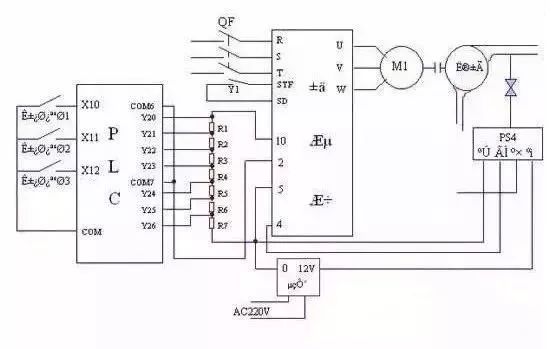
The digital input interface of the PLC is not complex. To improve anti-interference capability, PLCs use optocouplers to isolate the input signals from the internal processing circuits. Therefore, the signal at the input end only drives the internal LED of the optocoupler, which is received by the phototransistor of the optocoupler, allowing reliable transmission of external input signals.
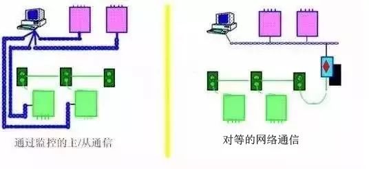
Currently, PLC digital input ports are generally divided into single-ended common point and dual-ended inputs. Due to these distinctions, users need to understand the wiring when selecting external sensors to correctly use sensors with PLCs, laying the foundation for subsequent programming and system stability.
2.Types of Input Circuits
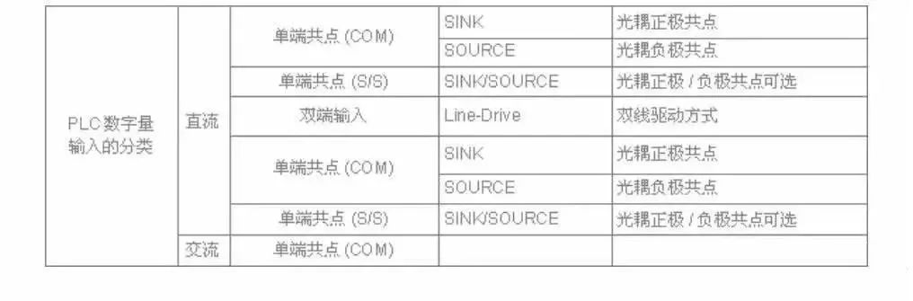
1. Classification of Input Types
The digital input terminals of the PLC are classified according to power supply into DC and AC. According to the input interface classification, there are single-ended common point and dual-ended inputs. A single-ended common point connected to the positive terminal of the power supply is referred to as SINK (sink current), while a single-ended common point connected to the negative terminal of the power supply is referred to as SRCE (source current).
2. Overview of Terms
The SINK type allows current to flow out from the input end. Therefore, the input end should be connected to the negative terminal of the power supply, indicating that the internal optocoupler is single-ended common point connected to the positive terminal, suitable for connecting NPN sensors.
The SOURCE type allows current to flow into the input end. Thus, the input end should be connected to the positive terminal of the power supply, indicating that the internal optocoupler is single-ended common point connected to the negative terminal, suitable for connecting PNP sensors.
Proximity switches and photoelectric switches with three or four wire outputs can be NPN or PNP outputs. When there is no detection signal, the NPN proximity switch and photoelectric switch output high level (considering internal pull-up resistors). When there is a detection signal, the internal NPN transistor conducts, and the switch output is low level.
When there is no detection signal, the PNP proximity switch and photoelectric switch output low level (considering internal pull-down resistors). When there is a detection signal, the internal PNP transistor conducts, and the switch output is high level.
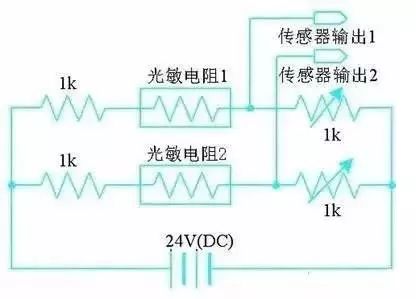
The above situations only apply when the sensors are in a normally open state.
3. Configuration Types by Power Supply
(1) DC Input Circuit
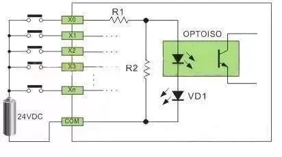
As shown in Figure 1, the DC input circuit requires that the external input signal elements be passive dry contacts or DC active non-contact switch contacts. When the external input element is connected to the positive terminal of the power supply, current flows through R1, the LED of the optocoupler, VD1 (interface indicator), to the COM terminal to form a loop. The phototransistor inside the optocoupler receives the signal from the external element to transmit it to the internal processing; this interface powered by DC is called a DC input circuit.
The DC power can be provided internally by the PLC or from an external DC power supply for the external input signal elements. R2 in the circuit serves to bypass the current of the optocoupler’s internal LED, ensuring that the optocoupler’s LED is not turned on by the static leakage current of the two-wire proximity switch.
(2) AC Input Circuit
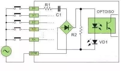
As shown in Figure 2, the AC input circuit requires that the external input signal elements be passive dry contacts or AC active non-contact switch contacts. The distinction from the DC interface is that a step-down circuit and bridge rectifier circuit are added before the optocoupler. After the external element is connected to the AC power, current flows through R1, C2 through the bridge rectifier, converting it into reduced DC, with the subsequent circuit principle consistent with that of DC.
AC PLCs are mainly suitable for relatively harsh environments where wiring techniques do not change significantly; for example, proximity switches can directly replace the original travel switches using AC two wires.
4. By Port Type
(1) Single-ended Common Point (Comcon) Digital Input Method
To save input terminals, the structure of single-ended common point input connects one end of all input circuits (optocouplers) inside the PLC to an internal common terminal labeled COM. The other end of each input circuit is then connected to its corresponding input terminals X0, X1, X2, …
Common points with N single-ended inputs can create N digital inputs (N+1 terminals), thus we refer to this structure as “single-ended common point” input. Users must also follow the same practice when wiring external digital input components, connecting one end of all input components together, referred to as external common wiring; the other end of the input components is connected to the PLC input terminals X0, X1, X2, …
The SINK input method can connect to NPN sensors, meaning the X terminal is connected to the negative terminal.
The SRCE input method can connect to PNP sensors, meaning the X terminal is connected to the positive terminal of the entire machine. (External input components can include push buttons, travel switches, reed switches, Hall switches, proximity switches, photoelectric switches, light curtain sensors, relay contacts, contactor contacts, and other switching components.)
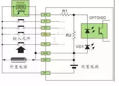
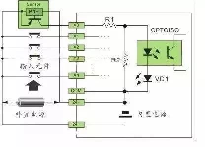
(2) SINK (sink current) Input Method ● Single-ended Common Point SINK Input Wiring (Internal Common Point Terminal COM → 24V+, External Common Wiring → 24V-). As shown in Figure 3:
(3) SRCE (source current) Input Method
● Single-ended Common Point SRCE Input Wiring (Internal Common Point Terminal COM → 24V-, External Common Wiring → 24V+). As shown in Figure 4:
(4) Switchable SINK/SRCE Input Method
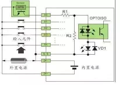
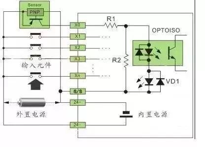
The S/S terminal is different from the COM terminal in that COM is fixedly connected to the internal power supply positive or negative terminal, while the S/S terminal is non-fixedly connected, depending on the need to connect to the positive or negative terminal of the internal or external power supply.
● Single-ended Common Point SINK Input Wiring (Internal Common Point Terminal S/S → 24V+, External Common Wiring → 24V-).
● Single-ended Common Point SRCE Input Wiring (Internal Common Point Terminal S/S → 24V-, External Common Wiring → 24V+).
(5) When there are many active input elements (Hall switches, proximity switches, photoelectric switches, light curtain sensors, etc.) consuming considerable power, and the built-in power supply of the PLC cannot meet the demand, an external power supply is required. Depending on the requirement, a 24VDC switch power supply of sufficient power can be configured. The external power supply should not be connected in parallel with the internal power supply. According to the characteristics of COM and external common wiring, in the SINK (sink current) input method, the external power supply is connected to the positive terminal of the internal power supply; in the SRCE (source current) input method, the external power supply is connected to the negative terminal of the internal power supply.
(6) A simple way to determine the SINK (sink current) input method is to short-circuit the Xn terminal with the negative terminal; if the interface indicator lights up, it indicates that it is the SINK input method. The common positive optocoupler can connect to NPN sensors. For the SRCE (source current) input method, short-circuit the Xn terminal with the positive terminal; if the interface indicator lights up, it indicates that it is the SRCE input method. The common negative optocoupler can connect to PNP sensors.
(7) For two-wire switching inputs, if they are passive contacts, the SINK and SRCE should be connected according to the input element wiring shown above. For two-wire proximity switches, it is necessary to determine the polarity of the proximity switch for correct connection.
(8) High-speed Dual-ended Input Circuit
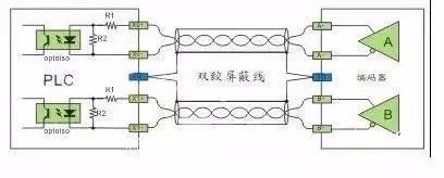
This is mainly used for the input of hardware high-speed counters (HHSC). The interface voltage is 5VDC, and to ensure high speed and high noise resistance, a dual-line drive method (Line-Drive) is usually employed. If the working frequency is not high and noise is low, a 5VDC single-ended SINK or SRCE connection can be used, with a current-limiting resistor in series to convert it to a 24VDC single-ended SINK or SRCE connection.
(9) Dual Input End Dual-Line Drive Method (Line-Drive).
(10) 5VDC Single-ended SINK or SRCE Connection.
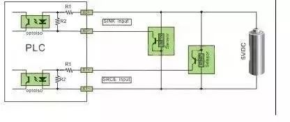
(11) 24VDC Single-ended SINK or SRCE Connection.
Note: For sensors powered by 24VDC, a current-limiting resistor needs to be connected in series on the input circuit, with R1 being 10Ω and R2 being 2KΩ. If no current-limiting resistor is used, it will burn out the interface circuit; the current-limiting resistor value should be 2.7KΩ.
3.External Input Elements
1. Passive Dry Contacts (Push Buttons, Travel Switches, Reed Magnetic Switches, Relay Contacts, etc.)
Passive dry contacts are quite simple and easy to wire. There are no issues with power supply polarity or voltage drop, as shown in the input elements in Figures 3-6. This will not be repeated here.
2. Active Two-Wire Sensors (Proximity Switches, Active Reed Magnetic Switches)
Active two-wire proximity switches are divided into DC and AC. The characteristic of this sensor is that it has two wires, and when the output end is conductive, a holding voltage is required to maintain normal operation, usually within a voltage drop of 3.5-5V, with a static leakage current of less than 1mA, which is an important specification; if it is too large, the optocoupler at the PLC input end will conduct when there is no detection signal.
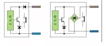
DC two-wire proximity switches are divided into diode polarity protection and bridge rectifier polarity protection. The former requires attention to polarity when connecting to the PLC, while the latter does not need to consider polarity. Active reed magnetic switches are mainly used for position detection on cylinders and do not require attention to polarity due to the need for signal indication, as they have a bidirectional diode loop inside; AC two-wire proximity switches also do not require attention to polarity. As shown in Figure 10:
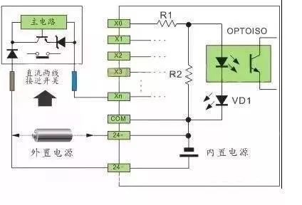
(1) Single-ended Common Point SINK Input Wiring (Internal Common Point Terminal COM → 24V+, External Common Wiring → 24V-). As shown in Figure 11.
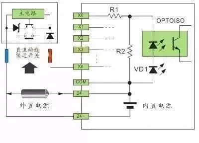
(2) Single-ended Common Point SRCE Input Wiring (Internal Common Point Terminal COM → 24V-, External Common Wiring → 24V+). As shown in Figure 12:
(3) The S/S terminal connection method refers to Figures 5-6 and 11-12.
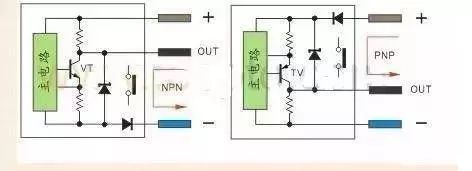
3. Active Three-Wire Sensors (Inductive Proximity Switches, Capacitive Proximity Switches, Hall Proximity Switches, Photoelectric Switches, etc.) Active three-wire proximity switches and photoelectric switches use transistors for output, so sensors are divided into NPN and PNP outputs. Some products are four-wire, with double NPN or double PNP outputs, which are just opposite in state, and there are also four-wire outputs combining NPN and PNP.
The NPN type outputs current to the negative terminal when the sensor detects a signal VT, making the output terminal OUT’s potential close to the negative terminal, usually referred to as high level switching to low level.
The PNP type outputs current to the output terminal OUT when the sensor detects a signal VT, making the output terminal OUT’s potential close to the positive terminal, usually referred to as low level switching to high level.
The resistance at the emitter of the transistor in the circuit is a short-circuit protection sampling resistor of 2-3Ω, which does not affect the output current. The resistance at the collector of the transistor is a pull-up and pull-down resistor, providing output potential for easy interfacing with level circuits; another type of output from the transistor collector is open-collector output without pull-up and pull-down resistors.
In simple terms, when the transistor VT conducts, it is equivalent to a contact closing, as shown in Figure 13:
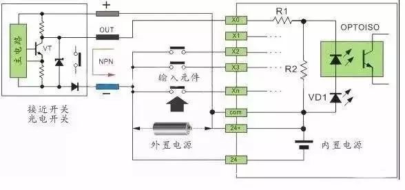
(1) Single-ended Common Point SINK Input Wiring (Internal Common Point Terminal COM → 24V+, External Common Wiring → 24V-). As shown in Figure 14:
(2) Single-ended Common Point SRCE Input Wiring (Internal Common Point Terminal COM → 24V-, External Common Wiring → 24V+). As shown in Figure 15:
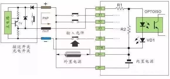
(3) The S/S terminal connection method refers to Figures 5-6, 11-12, and 14-15.
Due to the diversity of PLC input interface circuit forms and the output signal forms of external components (sensors), it is essential to understand the PLC input circuit forms and the sensor output signal forms before wiring the PLC input module to ensure correct wiring. This understanding will facilitate practical application and lay the foundation for subsequent programming and system stability.
Disclaimer: This article is reprinted from the internet, and the copyright belongs to the original author. If there are any copyright issues, please contact us promptly for deletion. Thank you!
HISTORY/Previous Recommendations
Complete question bank for the 2021 Electrician Junior Examination (with answers)
Is troubleshooting frequency converter faults difficult? Just one click!
Can you sweep through all electrical exam questions with one click? Don’t you have this tool yet?
Which of the five major electrical drawing software (CAD, Eplan, CADe_simu…) do you prefer?
Latest electrical CAD drawing software, with a super detailed installation tutorial!
Latest electrical drawing software EPLAN, with a super detailed installation tutorial!
Common issues for beginners using S7-200 SMART programming software (with download link)
Super comprehensive electrical calculation EXCEL spreadsheet, automatically generated! Electrical calculations made easy!
Bluetooth headphones, electrician/PLC beginner books are freely given away? Come and claim your electrical gift!
Basic skills in PLC programming: Ladder diagram and control circuit (with 1164 practical cases of Mitsubishi PLC)
Can’t understand electrical diagrams? Take the basics of electrician diagram recognition and simulation software for quick hands-on!
12 free electrician videos, 10GB software/e-book materials, and 30 days of free electrician live courses are being given away!
Don’t forget to like + check it out!