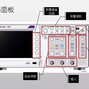
How Are Circuit Boards Made? Equipment Needed in Production

How are circuit boards made? The production process of PCB boards can be roughly divided into: Printed circuit board—inner layer circuitry—lamination—drilling—plating through holes (first copper)—outer layer circuitry (second copper)—solder mask green paint—text printing—contact processing—shaping and cutting—final inspection and packaging. So there are many devices involved; what equipment does PCB need? Generally, the production of PCB … Read more

Understanding Multi-layer PCBs: A Comprehensive Guide

Understanding Multi-layer PCBs: A Comprehensive Guide

When hardware engineers first encounter multi-layer PCBs, it can be quite overwhelming. With sometimes ten or more layers, the layout resembles a spider web. Are you still struggling? Today, I’ve created several internal structure diagrams of multi-layer PCBs, using 3D graphics to display various stacking structures of PCB internal architecture, helping you to see clearly. … Read more

How to Build Circuit Boards: A Beginner’s Guide

How to Build Circuit Boards: A Beginner's Guide

Search WeChat Technical Training Comparison of Breadboards and Universal Boards Welding Methods for Universal Boards For the layout of components on the universal board, most people are accustomed to “following the clues,” centering around key components like chips and inserting other components wherever possible. This method reflects order in the chaos of soldering, and is … Read more

PCBA Circuit Board PIP Through-Hole Soldering Technology

PCBA Circuit Board PIP Through-Hole Soldering Technology

Error Proofing and Foolproofing (Industrial Design Case Sharing) (Click the above blue text to obtain learning materials!) (High Transparency Soldering Case – Automotive Control Products) Source:Electronic Manufacturing Process Technology http://www.dianzichanye.com Recommended Reading Decoding Foxconn IE Seven Practical Techniques of IE Introduction to Gas Tightness Testing Technology Classification and Application of Water-Based Cleaners IPC-A-610G Standard Training … Read more

Understanding Various Symbols on Circuit Boards

Understanding Various Symbols on Circuit Boards

On many circuit boards or electronic products, we often see the following symbols, for example: FCC, CE, Hand Symbol, and Trash Can Symbol on Atmel Development Boards RoHS and RU Symbols on NXP Development Boards Hand Symbol, Trash Can Symbol, and Pb Symbol on NXP Development Boards CE and FCC Symbols on Arduino Development Boards … Read more

Why PCBA Testing Is Essential After Circuit Board Processing

Why PCBA Testing Is Essential After Circuit Board Processing

Click the blue text above to follow us During the electronic manufacturing process, PCBA testing is a crucial step. Whether for consumer electronics, industrial equipment, or automotive electronics, PCBA testing ensures the product’s quality, reliability, and functionality. The main reasons for conducting PCBA testing after the circuit board processing are as follows.1. Ensure Circuit FunctionalityThe … Read more

Why Design Test Points on Circuit Boards?

Why Design Test Points on Circuit Boards?

Some Testing Service Projects: Materials: Physical Properties, Chemical Analysis, Biological Tests Reliability Testing of Components and Finished Products Formula Analysis, Formula Restoration Failure Analysis Product Certification National Customer Service Number: 4008180021 Add Customer Service WeChat anytesting001 to get daily R&D news The following is the main text: For those studying electronics, setting up test points … Read more

Troubleshooting Inverter Circuit Boards

Troubleshooting Inverter Circuit Boards

Troubleshooting Inverter Circuit Boards Generally speaking, the printed circuit boards on an inverter mainly include the drive board, main control board, and display board. The factors affecting the lifespan of the inverter’s printed circuit boards include the lifespan characteristics of the smoothing capacitors in the power supply section and the buffer capacitors in the IPM … Read more

Embedded Communication Principles – SPI Bus Communication Principles and Applications

Embedded Communication Principles - SPI Bus Communication Principles and Applications

Click the Blue Text Follow Us Introduction to SPI SPI (Serial Peripheral Interface) is a synchronous serial communication protocol used for data transmission between devices over short distances. It is commonly used for communication between microcontrollers and external devices such as sensors, flash memory, displays, etc. SPI has the following main characteristics: Basic Principles SPI … Read more