
Hello everyone, I am a beginner in electronics. Today we will analyze an AC 220V to DC 5V resistive-capacitive voltage reduction circuit.
The resistive-capacitive voltage reduction is a circuit that can convert AC mains power to low DC voltage with very few components and at a very low cost. It is often used in devices where space is limited and cost is sensitive.
This circuit is one I saw many years ago; it is a very classic circuit, the source is unclear, but it is simple yet practical.
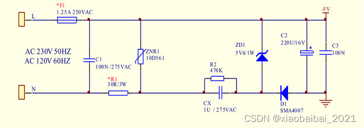
I have redrawn it in Multisim for simulation analysis, as shown in the figure below:
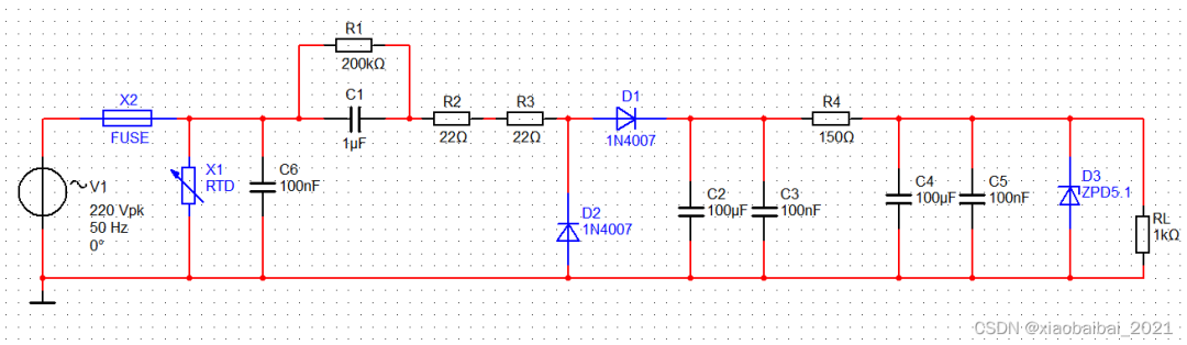
Next, we will divide this circuit into several parts and analyze each one.
First, let’s look at the leftmost part:
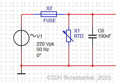
After the AC 220V mains input, it first passes through a fuse X2, which provides overcurrent protection. Then it goes through X1 and C1; X1 is a varistor (since the Multisim software does not have a varistor component, I used a sliding rheostat as a substitute), mainly used for surge protection and lightning protection; C6 is a safety capacitor used for filtering.
The functions of these three components are to enhance the safety and electromagnetic compatibility of the circuit.
Next comes the combination of R1 and C1, as well as R2 and R3:
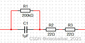
Capacitor C1 is used for voltage reduction in the circuit because capacitors can pass AC, but ideally do not consume power. Therefore, a capacitor with a certain capacitance value is chosen, which has a certain capacitive reactance when AC passes through; this reactance effect is in series with the subsequent circuit, dividing off a portion of the voltage, thus achieving voltage reduction. C1 selection is very critical for the entire circuit; its capacitive reactance calculation formula is Rc=1/(2πfC), and the capacitive reactance must be divided with the downstream resistance to obtain an appropriate output. C1 must have a voltage rating of at least 400V, and it should be a non-polarized capacitor, such as CL21 polyester or CBB21 polypropylene capacitor.
Resistor R1 is used for discharging C1 to ensure that the voltage across C1 can be quickly released after power is disconnected. It is generally required that R1*C1<T, where T is the time constant related to the mains frequency, typically chosen to be less than 300ms. The voltage rating of R1 must exceed the maximum mains voltage.
R2 and R3 are for protection, preventing high voltage damage to the downstream circuit when there is poor contact and when C1 is charged with the mains voltage. Generally, based on experience, the sum of the two is taken to be between 40~50Ω.
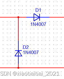
Next are the two diodes D1 and D2, which form a simple half-wave rectification circuit. In fact, a full-wave rectifier bridge could also be used here, but two diodes save costs.
It is important to note that the selected diodes must have sufficient voltage and current ratings.
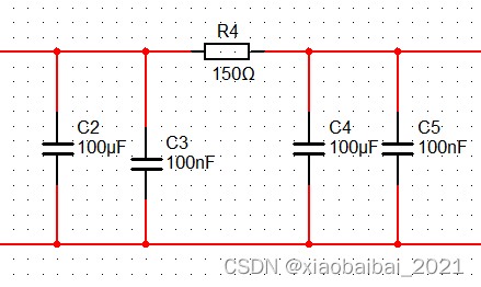
Next is the filtering part below, which is also quite simple, consisting of RC filtering.
It is necessary to pay attention to the value of R4, as there will be current flowing through R4; if the value is too high, it will waste a lot of power, but if the value is too low, it will weaken the filtering effect and cannot work in conjunction with the downstream voltage regulator, so it needs to be considered comprehensively.
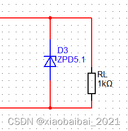
Finally, we have the voltage regulator and load; the voltage regulator needs to interact with the preceding R4 resistor to function properly. When selecting D3, choose the voltage regulator that is closest to the required voltage value.
It is also important to note the power rating of the voltage regulator, as the output voltage is adjusted by the voltage regulator. The current changes in this part of the circuit with and without load must be regulated by the voltage regulator, so it is necessary to verify whether the voltage regulator can still operate in a regulated state under maximum and minimum output power conditions.
Alright, the circuit analysis is complete. In fact, the core of the entire circuit is to achieve the functions of voltage reduction, rectification, filtering, and voltage regulation.
Let’s do a simulation of the circuit:
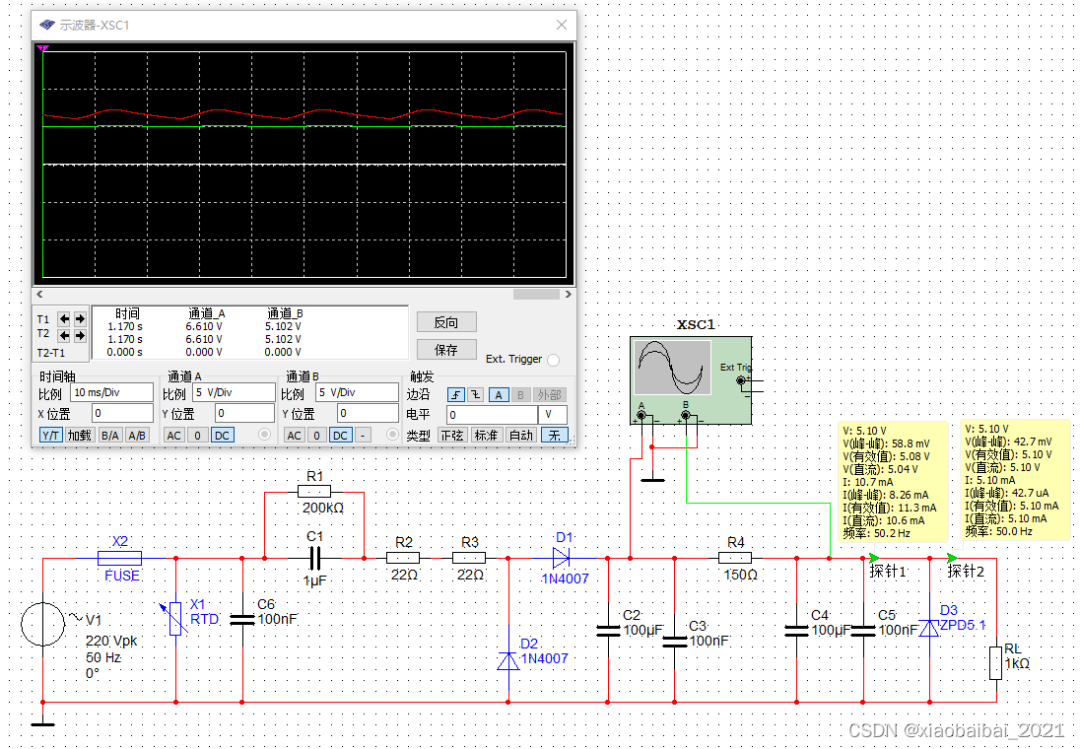
As can be seen, after half-wave rectification and capacitor filtering, the voltage is approximately between 6V and 8V; after RC filtering and voltage regulation, it stabilizes around 5.1V with very slight fluctuations.
At the same time, it is also noted that in this state, when the load current is very small, most of the current passes through the voltage regulator, resulting in relatively low efficiency. When the load current increases, it can be anticipated that the voltage drop across R4 will also increase, which may cause the voltage at the voltage regulator to fail to reach 5.1V. Therefore, resistive-capacitive voltage reduction circuits are not very suitable for situations with large load variations, generally used in scenarios where the load is relatively constant.
In addition, since the resistive-capacitive voltage reduction circuit, even after voltage reduction, still has one end directly connected to the AC mains 220V line, it poses a certain risk of electric shock and should generally only be used in situations where humans will not come into contact with it.
Besides the form analyzed above, there are many other implementations of resistive-capacitive voltage reduction, but their core mostly adopts capacitive series voltage reduction, followed by rectification, and finally filtering and voltage regulation. Here I have collected some similar circuits for those interested to analyze:
The following circuit simplifies the filtering circuit:
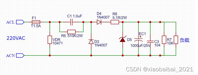
The following circuit uses the voltage regulator for rectification as well, saving one diode; and the filtering circuit is also simplified:
Alright, that concludes this section.
If you find it useful, feel free to follow my WeChat public account: “Xiaobai Bai Learns Electronics”, where you can download related learning resources: