To acquire information from the external environment, humans must rely on sensory organs. However, relying solely on human sensory organs is inadequate for studying the laws of natural phenomena and production activities. To adapt to this situation, sensors are required. Therefore, it can be said that sensors are an extension of human senses, also known as electrical senses.
In modern industrial production, especially in automated production processes, various sensors are used to monitor and control various parameters during the production process, ensuring that equipment operates in a normal or optimal state and that products achieve the best quality. Thus, without numerous high-quality sensors, modern production would lose its foundation.
Each type of sensor module has its core components and auxiliary circuits, such as the photoresistor in the light-sensitive resistor sensor, which is the soul of the entire module. It serves as a bridge between the circuit and the external environment, while the auxiliary circuit unit is merely for simple processing of input and output, ensuring that sensitive components and module ports can interface safely and transmit data normally. Most sensors measure physical or chemical quantities that are analog in nature; thus, the auxiliary circuit greatly contributes to providing expected outputs (for example, converting analog signals into digital signals). The reason for packaging them into modules is to facilitate users in directly using the output quantities from the ports to achieve expected functions, saving time in designing, producing, and debugging circuits.
Today, I will introduce you to the common types of sensor modules available in the market and their simple working principles! Of course, each type of sensor has different models; the article only provides one example for each type of sensor, as the principles and usage methods of various similar sensor modules are largely the same. The following classifications are roughly categorized based on the characteristics of the physical or chemical quantities they measure, so please don’t get too caught up in the details!!!
Here are some common port labels and terms found on modules:
VCC: Positive power supply (generally 5V)
GND: Negative power supply (0V)
AO: Analog output
DO: Digital output
OUT: Output
Switching signal: High and low levels
In general, various sensitive components measure analog signals. To convert these analog signals into digital signals for microcontroller use, most modules utilize the LM3983 chip and related circuits. The appearance and internal logic circuit of the LM393 chip are shown in the figure below.
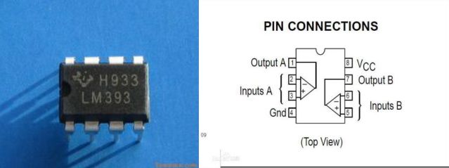
LM393 is a dual voltage comparator with 8 pins. When the notch of the chip is facing upwards (as shown in the top right), the upper right corner is VCC, and the lower left corner is GND. These two pins provide conditions for the chip to operate normally; the remaining 6 pins are divided into two groups, each containing a comparator with two input terminals and one output terminal. When the voltage at the “+” terminal of the comparator is greater than that at the “-” terminal, the output terminal, Output A & Output B, outputs a high level; otherwise, it outputs a low level. Utilizing this feature, it is often used to detect voltage changes and control the switch of a circuit. For specific circuits and detailed usage methods, please search online.
Optical Sensor Modules:
1. Light-sensitive Sensor Module:
The light-sensitive sensor is one of the most common sensors;
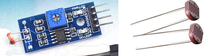
Its core component—the light-sensitive resistor can convert light signals (light intensity) into electrical signals (the resistance of the light-sensitive resistor); then, the comparator circuit compares the voltage across the light-sensitive resistor with the voltage across the potentiometer and outputs a high or low voltage to the DO port for user use; the AO port directly outputs the voltage after the light-sensitive resistor has been reduced, so it outputs any voltage value between GND and VCC. Of course, VCC and GND are essential conditions for the normal operation of the module’s components and chips and cannot be omitted!!! The light-sensitive sensor is commonly used in automatic camera aperture adjustment or automatic streetlight switches.
2. Infrared Obstacle Avoidance Module
The infrared obstacle avoidance module has auxiliary circuits that are basically the same as those of the light-sensitive sensor (both have the LM393 chip and surrounding circuits); the core components are the infrared emitting tube (the transparent component in the image) and the infrared receiving tube (the black component), which emits infrared rays at a certain frequency;
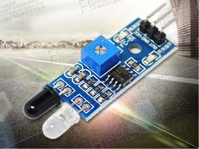
When the emitted infrared rays are reflected by an obstacle in front, the receiving tube receives the infrared rays, at which point the comparator circuit compares the voltage across the receiving tube and the potentiometer, performing the same output operation as the light-sensitive sensor module (outputting the corresponding electrical signal from the OUT pin). The infrared obstacle avoidance module is commonly used to make smart cars, such as the road detection part of a line-following car or the obstacle detection part of an obstacle-avoiding car.
3. Line Following Sensor Module
It can be clearly seen that the line-following sensor module also contains a comparator circuit, which works similarly to the infrared obstacle avoidance module, emitting infrared rays—infrared rays encounter obstacles and reflect—receiving infrared rays;

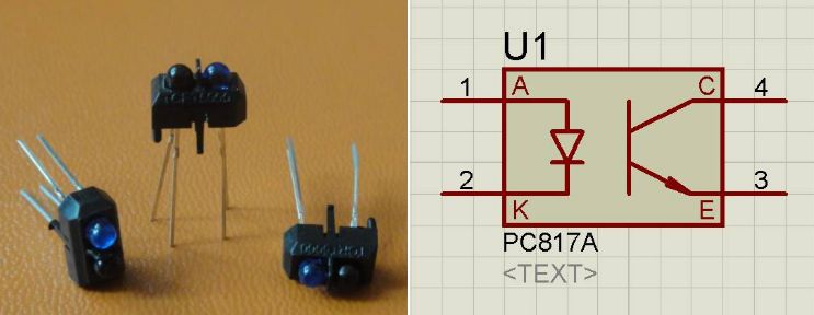
Its core component is the infrared pair tube, which consists of an infrared emitting tube and an infrared phototransistor. The working principle of the infrared phototransistor is similar to that of common PNP/NPN transistors. The difference between it and the infrared diode is that it converts light signals into electrical signals while amplifying the current; it only receives light, not electricity. As long as it receives light, current will flow from one end of the infrared phototransistor to the other; the emitting tube and receiving tube of the infrared pair tube are fixed and separated by a plastic shell to avoid unnecessary interference from the infrared rays emitted directly being received by the infrared phototransistor. This module is designed for making line-following cars, so the detection part and other circuit units are on different sides of the PCB board (the detection part facing the ground and the circuit on the other side), allowing for easy observation of the status of the indicator lights on the circuit board without worrying about electronic components colliding or getting wet and damaged.
4. U-Shaped Photoelectric Sensor Module
The U-shaped photoelectric sensor module is also called a slot-type optocoupler module, speed sensor module, or counter module;
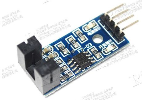
It also contains a comparator circuit. Unlike the above several comparator circuits, this module does not have a potentiometer because the above modules have strict environmental requirements (for example, sunlight and lamp light can affect their receiving end). To achieve the expected effect, the potentiometer must be adjusted according to the actual external conditions. The U-shaped slot photoelectric module directly places the receiving tube and emitting tube on opposite sides, each packaged in a plastic shell, leaving only a small gap for emitting and receiving infrared light, thus reducing external interference and allowing for a surface-mounted resistor to directly replace the potentiometer, reducing costs, minimizing size, and achieving the expected effect;
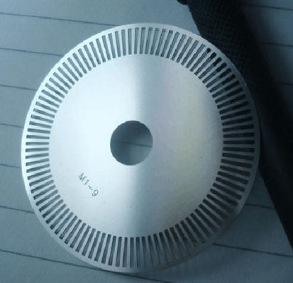
The counter module is not used alone but is often used in conjunction with a speed encoder, the appearance of the speed encoder is the circular object shown in the image above, generally made of plastic; the encoder is fixed on the rotating shaft, and the gaps on the periphery of the encoder are placed in the U-shaped slot between the photoelectric module. The components at both ends of the U-shaped slot work on principles similar to those of the infrared pair tube, except they are placed on either side of the U-shaped slot with a small gap for light transmission. When the grating on the periphery of the circular disk blocks the infrared light, the OUT pin of the module outputs a switching signal, and when the gaps in the grating are between the U-shaped slot, the module outputs the opposite switching signal. Since the rotational situation of the encoder can be calculated mathematically, the speed of the bearing and other connected mechanical objects’ angular or linear velocity can also be calculated based on the actual mechanical structure.
5. Infrared Receiving Module
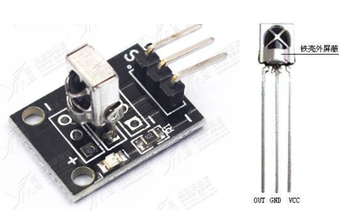
The infrared receiving module is used to receive infrared signals, generally used to receive digital infrared signals, such as those emitted by television remote controls; the infrared receiving circuit is usually integrated by manufacturers into a single component, including infrared detection diodes, amplifiers, etc., forming an integrated infrared receiver. The infrared receiver requires VCC and GND to provide working conditions; when it receives infrared signals, it outputs a low level at the OUT pin, while the OUT pin is high level when idle. Since natural light often contains infrared and other wavelengths of light, infrared receivers are often packaged in black plastic to shield interference from infrared rays in natural light, and using a metal casing can block some light, allowing the receiver to receive infrared signals within a certain angle.
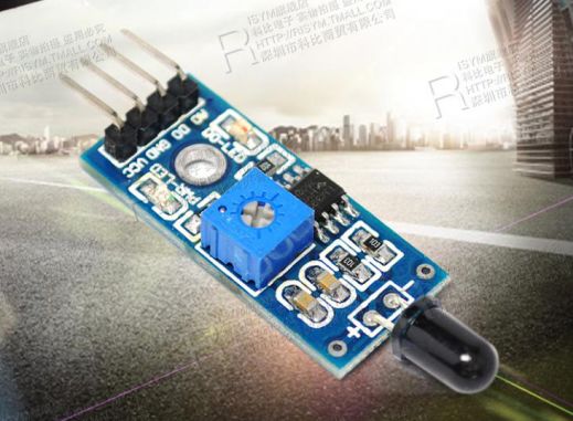
6. Flame Sensor Module
Since the light of flames contains a large amount of infrared rays, the infrared receiving device can directly receive external light and then use the module’s comparator circuit to determine if a fire has occurred; the module below has 4 terminals, where VCC is the positive power supply, GND is the negative power supply, AO directly outputs the detected analog value, and DO outputs the switching value judged by the LM393 chip.
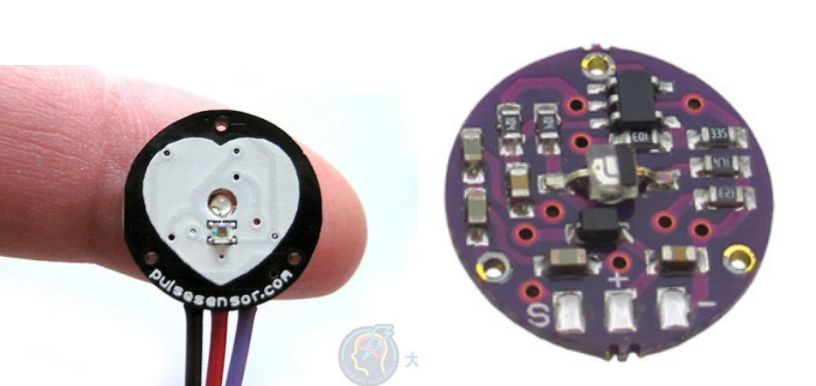
7. Pulse Sensor
The pulse sensor has two output methods: analog output and digital output. According to the method of signal acquisition, it can be mainly divided into piezoelectric, piezoresistive, and photoelectric types; among them, piezoelectric and piezoresistive types convert the pressure process of pulse beating into signal output through micro-pressure type materials (piezoelectric sheets, bridges, etc.). The photoelectric pulse sensor converts the change in light transmittance of blood vessels during pulse beating into signal output through reflection or transmission; pulse sensors are mainly used in medical devices, educational equipment, and teaching training fields, such as blood oxygen measurement, heart rate monitoring, and traditional Chinese medicine pulse diagnosis.
8. Camera Module
The core component of the camera module is a small light-sensitive element embedded inside the lens, also known as an image sensor; the quality of the image transmitted by the module is directly related to the precision of this light-sensitive element; there are mainly two types of light-sensitive elements: CCD (Charge-Coupled Device) and CMOS (Complementary Metal-Oxide-Semiconductor). Most digital cameras in mobile phones use CMOS sensors;
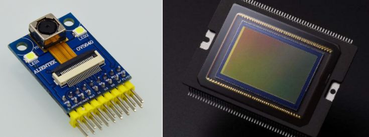
CCD is a highly photosensitive semiconductor material composed of many light-sensitive units, usually measured in millions of pixels. When the surface of the CCD is illuminated, each light-sensitive unit reflects the charge onto the component, converting light into charge. The signals generated by all the light-sensitive units combine to form a complete image, which is then converted into a digital signal, compressed, and stored in the camera’s internal flash memory or built-in hard disk card.
CMOS manufacturing technology is not much different from that of general computer manufacturing technology; it mainly uses silicon andgermanium to create semiconductors, allowing N (negatively charged) and P (positively charged) level semiconductors to coexist on the CMOS, and the current generated by these two complementary effects can be processed and recorded by chips to form images.
Today, I will stop the introduction here; the remaining 22 sensor modules will be covered in the following two articles, so stay tuned!!!

Text: Chen Feng Li Zhengyang
Editor: Chen Feng Li Zhengyang
Guiding Teacher: Yu Jie