Click the “blue text” to follow us

The “Commodity Name and Coding Coordination System” (hereinafter referred to as the “Coordination System”) 2022 edition has added LCD modules. What components make up this module structurally? How does it differ from the familiar LCD monitors and LCD TVs? In fact, if one cannot distinguish between them, accurate classification of these products cannot be achieved, and there are significant tax differences corresponding to these categories. This article will analyze in detail the structural composition and classification of these products.
LCD Module
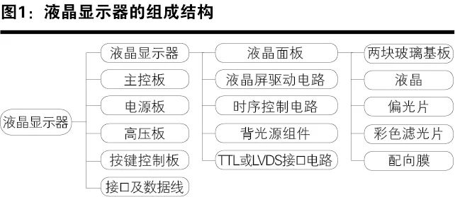
The LCD module (LCD module), also known in the industry as an LCD screen or panel, is the main component of an LCD monitor, whose function is to display clear images. The LCD module mainly includes the LCD panel, LCD screen driver circuit, timing control circuit, backlight component, TTL or LVDS interface circuit, etc. These parts are usually packaged within the same housing.
LCD Panel
The LCD panel (Cell) consists of polarizers (including two polarizers), color filters, two glass substrates (filled with liquid crystal material in between), and alignment films; among which, multiple TFTs are also made on the lower glass substrate (hence also called TFT array substrate), resembling a sandwich-like layered structure.
The role of the polarizer is similar to that of a fence, allowing only the components of light parallel to the fence to pass through, while the components perpendicular to the fence are blocked.
The color filter (Color film, i.e., CF) serves to color the LCD, typically placed on the transparent glass substrate. The color filter consists of a black matrix, color filter film (red, green, blue three primary colors), and ITO film (also known as transparent electrode).
The alignment film’s role is to arrange liquid crystal molecules in a predetermined direction and angle.
The thin film transistors (TFTs) in the TFT array substrate are used to control the direction or orientation of the liquid crystals.
LCD Screen Driver Circuit
The LCD screen driver circuit consists of row driver circuits and column driver circuits.
The column driver circuit processes pixel signals, applying parallel pixel signals row by row to the column electrode lines under pulse control.
The row driver controls the row electrode lines from top to bottom to display pixel signals row by row, ultimately forming an image; the circuit is relatively simple, functioning as a “displacement switch” controlled by row pulses.
Timing Control Circuit
The timing control circuit TCON (Timing Controller) is responsible for determining the order and timing of pixel displays and transmitting signals to the driver circuit.
Backlight Component
The backlight component (Back Light Unit, i.e., BLU) consists of lamps or LEDs, light guide plates, and reflectors. Since LCDs are passive display devices, the liquid crystals themselves do not emit light; they rely on modulating external light to display images. The external light is primarily sourced from the backlight, which mainly includes cold cathode fluorescent lamps (CCFL) and light-emitting diodes (LEDs). Thus, CCFLs and LEDs serve as the light sources for the backlight component, while the light guide plate and reflector are designed to distribute the backlight’s light evenly across the entire screen.
LCD Display Interface Circuit
Currently, the most commonly used LCD display interface circuits are TTL (Transistor Transistor Logic) and LVDS (Low Voltage Differential Signaling).
The TTL interface circuit is a parallel bus interface circuit used to drive TTL LCD screens, with 24-bit and 48-bit parallel digital display signals depending on the resolution.
The LVDS receiving circuit is a high-speed serial bus interface circuit used to drive LVDS LCD screens. This type of interface has a higher transmission rate and lower electromagnetic interference compared to TTL, and also requires fewer data transmission lines, thereby simplifying the circuit structure.
Both TTL and LVDS interface circuits can be bent, thus also referred to as Flexible Printed Circuits (FPC).
LCD Monitor
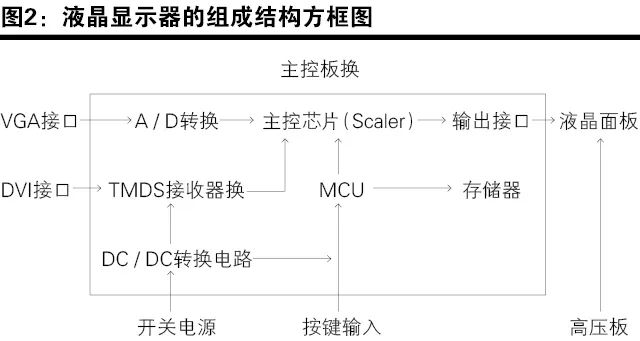
The LCD monitor mainly consists of the LCD screen, main control board, power board, high-voltage board, button control board, interfaces, and data lines. Figure 1 shows the structural composition of the LCD monitor, and Figure 2 is the block diagram of the structural composition of the LCD monitor.
Main Control Board
The main control board (also known as the driver board in the industry, not to be confused with the LCD screen driver circuit) is mainly used to receive and process the analog (VGA) or digital (DVI) image signals sent from external sources, generating the timing and voltage required to control the deflection of liquid crystal molecules, and sending out driving signals through the screen lines to control the operation of the LCD panel.
The main control board mainly includes the signal input section (connecting data lines), the signal output section (connecting screen lines), A-D conversion circuit (connecting VGA interface), TMDS receiver (connecting DVI interface), signal processing section (main control chip), microcontroller section (MCU and memory), control menu, and high-voltage board interface.
The signal input section mainly receives the analog (VGA) and digital (DVI) signals output from the computer graphics card.
The signal output section is the connection between the driver board and the display screen. Commonly used interfaces include parallel bus TTL interfaces and low-voltage differential LVDS interfaces.
The A-D conversion circuit is used to convert the analog signals output from the VGA interface into R, G, B digital signals, which are then processed by the image scaling circuit (Scaler).
TMDS (Transition Minimized Differential Signaling) is a differential signal transmission method that converts 8-bit R, G, B data signals into 10-bit line and field synchronization signals, clock signals, data DE signals, error correction signals, etc., which are then transmitted in a differential signal manner after DC balancing, achieving better electromagnetic compatibility compared to LVDS and TTL, thus enabling long-distance, high-quality digital signal transmission. The TMDS receiver is used to decode TMDS data and clock signals, which are then sent to the image scaling circuit for processing.
The signal processing section refers to the image scaling circuit of the driver board, which functions to transform signals of different resolutions into the corresponding resolution of the LCD screen, ensuring that the LCD screen displays normal images, as the pixel positions and resolutions of the LCD screen are fixed, while the resolutions of TV signals and externally input signals vary.
The microcontroller circuit mainly includes the microcontroller (MCU) and memory. Its role is to control the power switch and energy-saving state, frequency calculation, communication between various chips, character display control, etc. The microcontroller is essentially a single-chip microcomputer, integrating the CPU, RAM, ROM, timer, and various I/O interfaces into one chip. The memory (EEPROM) serves to store data and operational data required by the LCD display device.
The interfaces mainly include VGA and DVI interfaces. The VGA interface belongs to the 15-pin interface of computers, and its signals are analog signals, inputting RGB three primary color signals as well as horizontal and vertical synchronization signals. The DVI (Digital Visual Interface) interface conforms to the basic electrical connection method of the TMDS electronic protocol. On the left side of the interface are three rows of eight columns totaling 24 pins, and on the right side is one pin or four pins. The computer directly transmits display information to the display device in digital signal form.
Power Board
The power board converts the 90~240V AC voltage into 12V, 5V, 3.3V DC voltages to supply power to the driver board, LCD panel, etc. The power board mainly includes the DC/DC power circuit. The DC/DC power circuit converts the 12V (or 14V, 18V) and 5V DC voltages output from the switching power supply circuit into the 5V, 3.3V, 2.5V, 1.8V DC voltages required for the driving control circuit and the LCD panel to operate.
High Voltage Board
The high voltage board converts the 12V DC voltage output from the main board or power board into the 1500~1800V high-frequency high-voltage AC required to start and operate the backlight lamp. Some LCD monitors combine the power board and high voltage board. If the backlight source is LED, then the high voltage board is not needed.
Function Control Panel
The function control panel, also known as the button control board, is set up to achieve functions such as power on/off and menu adjustments (such as height, contrast, color, image position, etc.) for the LCD monitor.
LCD TV
The LCD TV mainly consists of power circuits, high-voltage inverters, high-frequency signal processing circuits, audio circuits, video decoding circuits, scan format conversion circuits, image scaling circuits, LCD display interface circuits, LCD screens, etc.
The block diagram of a typical LCD color TV is shown in Figure 3.
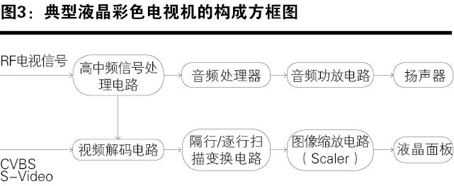
Since the power circuits, high-voltage inverters, image scaling circuits, LCD display interface circuits, and LCD screens in LCD TVs are similar to those in LCD monitors, the following will only introduce circuits unique to LCD TVs.
The high-frequency signal processing circuit converts radio frequency (RF) signals into composite video signals (CVBS) and secondary audio intermediate frequency signals, or directly outputs composite video signals (CVBS) and audio signals.
The audio circuit demodulates and processes the intermediate frequency signals from the second audio circuit, amplifying the power to drive the speakers and restore the audio signal.
The video decoding circuit functions to decode the composite video signals (CVBS) output from the intermediate frequency circuit to obtain brightness signals C and color difference signals UV, or brightness signals Y and three primary color signals RGB.
The scan format conversion circuit functions to convert interlaced scan image signals into progressive scan image signals and sends them to the image scaling circuit.
Classification Analysis of LCD Modules, LCD Monitors, and LCD TVs
In the revision of the 2022 edition of the “Coordination System”, a new item 85.24 for “Flat Panel Display Modules” has been added, along with a new note seven in Chapter 85, to clarify the scope, structural composition, and classification principles of this product.
Newly Added Provisions
7. The term “flat panel display module” in item 85.24 refers to devices or instruments used to display information, which must include at least one display screen and are designed to be installed in goods listed under other items before use. The display screen of the flat panel display module includes but is not limited to flat, curved, flexible, foldable, or stretchable types. The flat panel display module may include additional components necessary for receiving video signals and distributing these signals to the display pixels. However, item 85.24 does not include display modules equipped with components for converting video signals (e.g., image scaling integrated circuits, decoding integrated circuits, or program processors), or display modules that have characteristics of goods listed under other items.
The flat panel display module described in this note is classified under item 85.24, which takes precedence over other items.
Provision Analysis
◎ Function: Used for displaying information.
◎ Composition: Must include at least one display screen (e.g., the LCD panel consists of two glass substrates filled with liquid crystal); may include “components necessary for receiving video signals and distributing these signals to the display pixels”, i.e., the signal driving circuit of the display screen; must not include “display modules equipped with components for converting video signals (e.g., image scaling integrated circuits, decoding integrated circuits, or program processors) or display modules that have characteristics of goods listed under other items”, typically image scaling integrated circuits are included in LCD monitors, while decoding integrated circuits are included in LCD TVs; if they exhibit characteristics of goods listed under other items (e.g., item 85.31), they cannot be classified under this item.
◎ Can it be used independently: “Designed to be installed in goods listed under other items before use” indicates that this product is typically not used alone, but is installed in other goods (e.g., within displays or TVs listed under item 85.28), or it is a component of other goods.
◎ Priority classification: “Item 85.24 takes precedence over other items” indicates that goods under this item are classified preferentially.
The structure of the newly added item 85.24 is shown in Table 1.
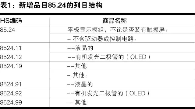
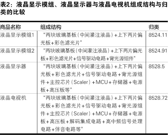
From the analysis of the product structure above, it can be seen that the LCD module composed of two glass substrates (filled with liquid crystal), two polarizers, and a color filter (i.e., the LCD panel in Figure 1, which is the industry term, but regardless of the name, the product name cannot serve as a basis for classification; the key to classification lies in its structural composition) belongs under item 8524.11 of the 2022 edition of the Coordination System as an “LCD module without driver or control circuits”.
If the LCD module is assembled with a display screen driver circuit and a backlight component (i.e., the LCD screen in Figure 1), it constitutes an “LCD module with driver” under item 8524.91; both item 8524.11 and 8524.91 LCD modules, regardless of whether they are equipped with touch screens.
If the LCD module is further assembled with a main control chip (Scaler), MCU, memory, power board, high-voltage board, etc., it constitutes an LCD monitor under item 8528.5.
If the LCD monitor is further assembled with decoding integrated circuits, high-frequency signal processing circuits, audio circuits, etc., it constitutes an LCD TV under item 8528.72.
In summary, the structural composition and classification comparison between the two types of LCD modules, LCD monitors, and LCD TVs are shown in Table 2.
Written by / Wen Zhao Zhu
(Shanghai Customs College)

Source: China Customs Magazine, November 2021