00 Notes
● Important considerations when using wireless energy-saving beacon lights:
-
Please keep away from personal items with magnetic or coil components, such as bus cards, bank cards,
NFCdevices, etc., to avoid damage; -
Please stay away from metal objects to prevent interference with the magnetic field, which may reduce charging efficiency;
-
When laying coils for smart cars, avoid placing them over metal objects on the track.
-
The power supply for the beacon controller is
7.5V/1A. Be careful when connecting; incorrect connections will cause damage!!! -
The transmitter must have the transmitting coil soldered before connecting to the
DC24V/5Apower supply; -
It is strictly forbidden to test the transmitter with a receiving coil that is not connected to a load, as it may easily damage the transmitter;
-
If the transmitting coil disconnects during operation, power should be immediately cut off;
-
The wireless transmission frequency is
150kHz, with a power transmission limit of50W(calculated based on a power transmission efficiency of70%).
1. Wireless Charging Transmitter Interface
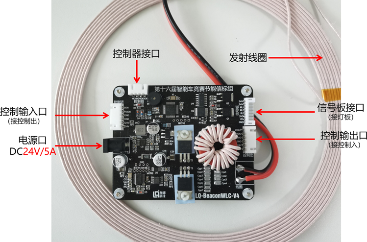
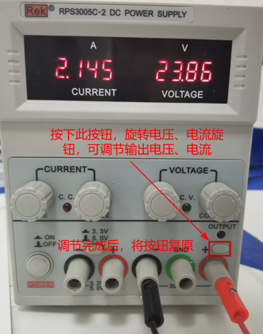
1. Working Power Supply: The power supply for the transmitter is 24V/5A. During the debugging process of the beacon system, the transmitter can be connected to the matching power supply or a digital adjustable power supply.
2. Digital Adjustable Power Supply: The firmware power limit for the beacon transmitter is 72W. When connected to 24V, the maximum current can reach 3A. It is prohibited to test the transmitter with a receiving coil that is not connected to a load.
3. External Transmitting Coil Specifications: It is recommended to use multi-strand yarn-wrapped wire with a diameter of about 2mm to wind a coil with a diameter of about 200mm, with 9 turns. The inductance is approximately 29uH.
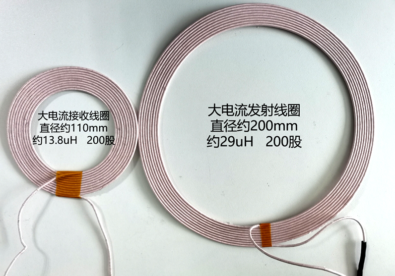
4. Recommended Receiving Coil Specifications: The receiving coil should be made of multi-strand yarn-wrapped wire with a diameter of about 2mm, wound into a hollow coil with an inner diameter of about 70mm and an outer diameter of about 110mm, with 10 turns. The inductance is approximately 13.8uH. Please design the receiving end resonant circuit based on the transmitter parameters.
2. Wireless Charging Controller Interface
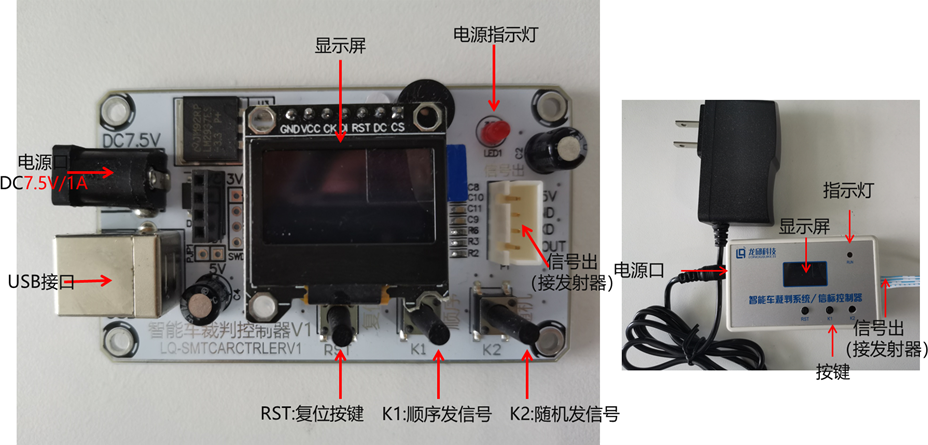
1. Working Power Supply: The power supply for the controller is 7.5V/1A. Always be careful when connecting the power supply; incorrect connections are strictly prohibited;
2. USB Interface: Use the provided USB cable to connect the computer and the controller interface to configure the controller parameters using the upper computer.
3. Signal Light Cover and Transmitter Protective Cover
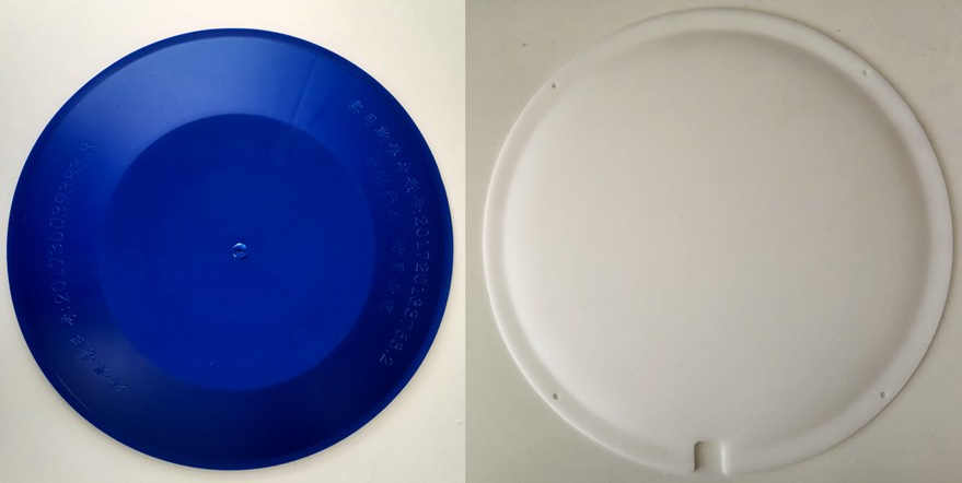
1. Beacon Light Cover: The beacon light cover is flat, with a diameter of 260mm and a height of 15mm, made of acrylic material. It has screw holes and wire exit notches. The cover is made of fragile material, so avoid heavy pressure during use.
2. Transmitter Outer Cover: The transmitter protective cover has a diameter of 285mm and a height of 20mm. It is made of plastic material. During use, the cover should be placed over the transmitter to protect it from collisions with vehicles. It can be secured to the track with tape.
4. Wiring Instructions
1. Wireless Charging Transmitter Operation Instructions
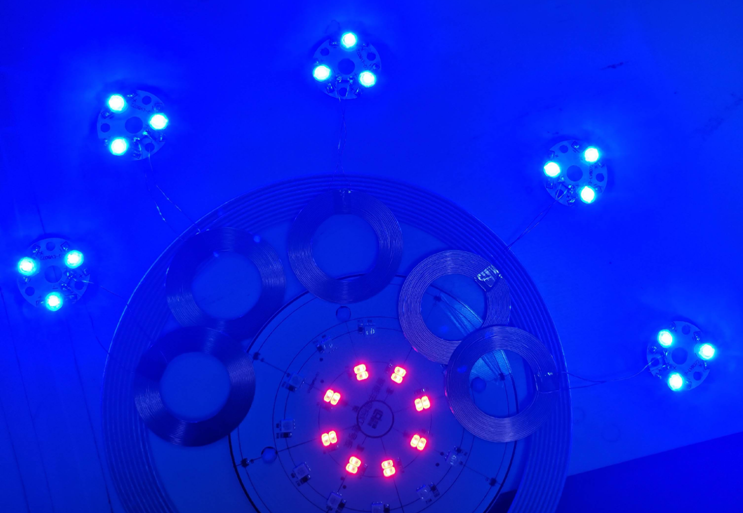
The wireless charging transmitter power port connects to the matching 24V/5A power supply. The first beacon light drives the transmitter and connects to the beacon controller via XH2.54-4P dual-head same-direction ribbon cable. The beacon light and the beacon driver transmitter are connected using PH2-8P same-direction ribbon cable. Once powered on, the signal light will flash and emit an infinite power signal. The light board is equipped with a Hall sensor, which will turn off the beacon light when it detects the magnetic signal. The second light and the first light are connected using XH2.54-6P same-direction ribbon cable, connected to the control output port of the first light beacon control board and the control input port of the second light beacon control board. The subsequent lights are connected in this manner. The beacon controller controls the lighting and wireless charging, guiding the energy-saving beacon car and enabling wireless charging.
Once the beacon is lit, it will simultaneously emit high-frequency wireless power signals and red, infrared light to guide the model car. The infrared light wavelength is 850 nanometers, and the red light flashing frequency is 40KHz. The high-frequency wireless signal sent through electromagnetic resonance charges the energy-saving model car and can also serve as a guiding signal to locate the light. The wireless charging transmitter outputs power of 70W/150KHz. The diameter of the transmitting coil is approximately 200mm, with an effective sensing range of 50mm horizontally and 100mm vertically around the coil. The closer to the center of the coil, the greater the received power. There are two scenarios for charging the model car:
(1) The beacon is in the lit state, and the transmitting coil sends wireless electrical energy. When the racing car enters above the transmitting coil, the model car begins to receive electrical energy. The onboard magnet triggers the Hall element in the beacon light, turning off the local beacon light and turning on the next beacon light. When the model car leaves the beacon light, the Hall element no longer detects the magnet, and the local transmitting coil stops sending wireless power signals.
(2) The beacon is in the off state, and the transmitting coil does not send wireless electrical energy. When the racing car enters above the transmitting coil, the onboard magnet triggers the Hall element in the beacon light, and the transmitting coil begins to send wireless power signals, allowing the model car to charge. When the model car leaves the beacon light, the Hall element no longer detects the magnet, and the transmitting coil stops sending wireless electrical energy.
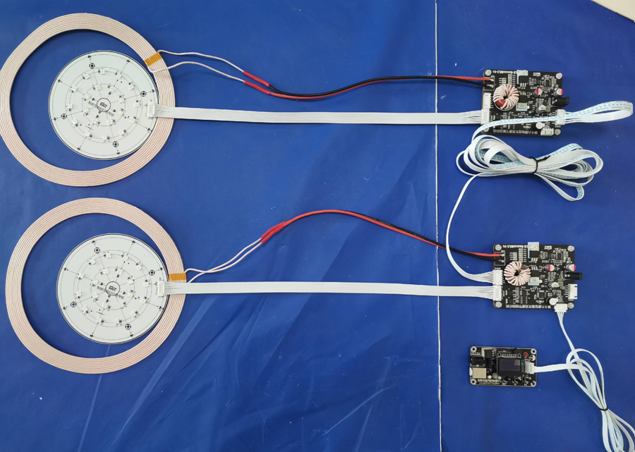
The diagram below shows the connection relationship of the beacon lights. The order of the lights is determined by the connection sequence to the controller. The controller at the bottom of the diagram is for the first light, while the controller above is for the second light.
2. Wireless Charging Controller Operation Instructions
The referee system / beacon controller uses the matching 7.5V/1A power supply (the power supply is already connected when the kit is sent out; incorrect connections are strictly prohibited!). After powering on, the controller indicator light will turn on, and the screen will display the number of connected beacon lights (Detector), trigger threshold (Threshold), and trigger dead time (Deadtime). The RST button controls the reset, the K1 button controls sequential lighting, and the K2 button controls random lighting.
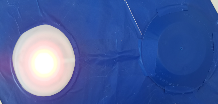
5. Testing the Transmitter Working Status
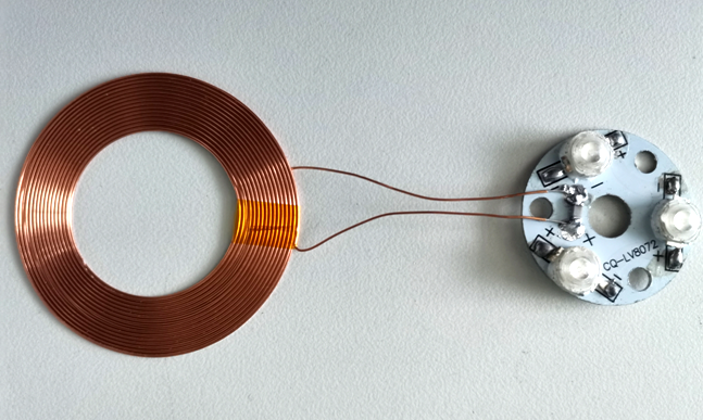
Using the wireless charging transmitter testing module, when close to the transmitting coil, the LED light will illuminate, indicating that the wireless charging transmitter has power output. This module can serve as a simple testing tool to check for power output or whether the transmitter is functioning properly.
6. Firmware Burning Process
When the functionality of the energy-saving wireless beacon light changes or upgrades, firmware (microcontroller program) can be downloaded from the supplier’s website for burning.
● Firmware Burning Conditions: Burning Software: J-Flash Burning Tool: ARMlink-V9 (Jlink-V9) Burning Target: Beacon Transmitter Wireless Charging Chip / Beacon Transmitter Communication Control Chip
1. Beacon Transmitter Burning Interface
The burning interface for the beacon transmitter wireless charging chip (XM1008F6P6) has the SWD burning interface from left to right as GND, CLK, DIO, VCC. During burning, the corresponding pin leads can be found from the downloader’s SWD interface.
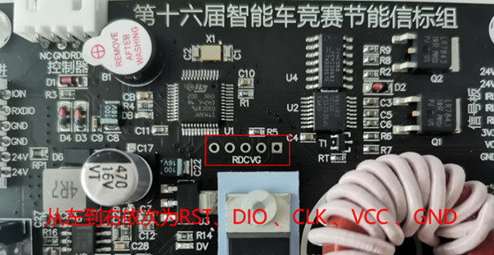
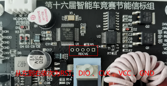
2. Beacon Transmitter Communication Control Chip Burning Interface
The burning interface for the beacon transmitter communication control chip (STM32F030C8) has the burning interface from left to right as RST, DIO, CLK, VCC, GND. During burning, the corresponding pin leads can be found from the downloader’s 10P interface.
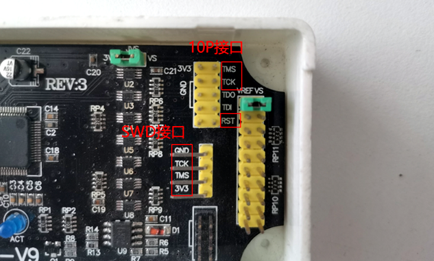
3. Downloader Interface
Use Dupont wires to connect from the downloader’s 4 pin SWD interface or from the 10P interface. The downloader interface has silk printing, and you can refer to the silk printing for connection. Among them, TCK corresponds to CLK, TMS corresponds to DIO, and the RST pin can be connected as needed. The interface is as follows:
4. Connecting the Downloader to the Transmitter Burning Interface
The transmitter firmware burning interface is not soldered with pin headers by default, so a male-to-female Dupont wire connection is required. You can connect as needed, as shown in the diagram:
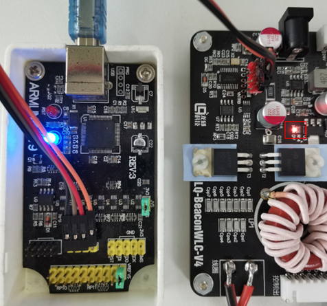
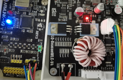
During burning, the beacon transmitter does not need to be connected to the 24V power supply. After connecting the Dupont wires, you will see the red indicator light on and the buzzer sounding.
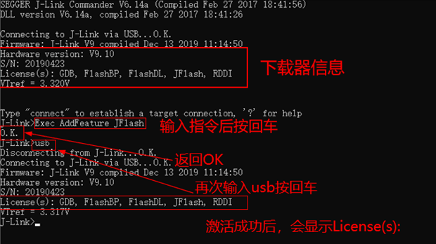
5. Activating the V9 Downloader’s J-Flash Burning Software Permissions
If you have not installed the jlink driver, please install the jlink driver first. It is recommended to install version V6.14 of the jlink driver (if using version V6.4 or higher, it may cause activation failure; uninstall and reinstall version V6.14 to resolve). After installation, plug in the V9 downloader, then find jlink commander in the “recently installed” section of your computer and open it. In the window, enter the activation command: “Exec AddFeature JFlash” and press “Enter”. If it returns OK, the activation is successful. You can enter “usb+” and press Enter to refresh the downloader information. Successful activation will prompt “License(s): GDB, FlashDL, JFlash, RDDI“
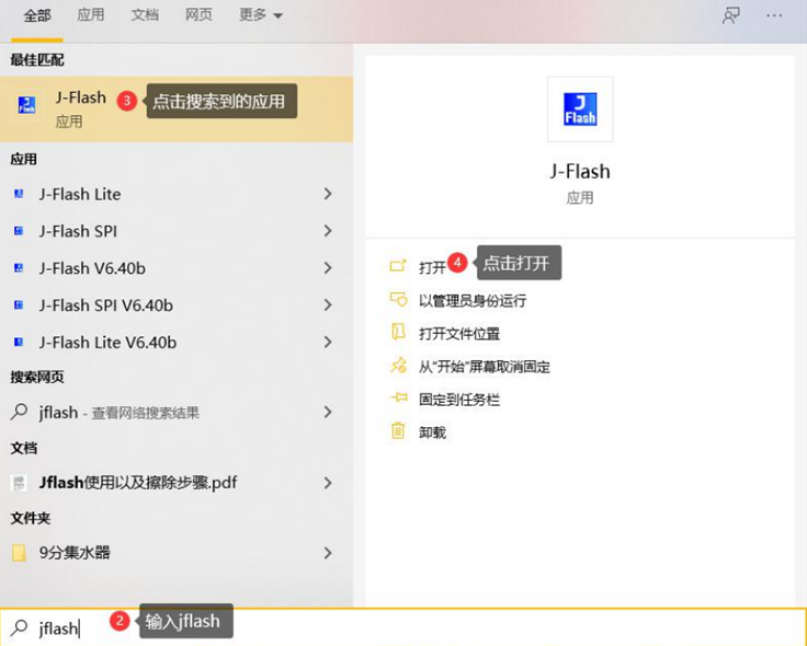
6. Opening the J-Flash Burning Software
After activation, find the J-Flash application in the recently installed section of your computer and open it, or search for jflash in the computer search bar and open it.
7. Opening the Project
After opening J-Flash, drag the .jflash file from the firmware data package into J-Flash. You will see the firmware project. Verify that the chip model on the beacon transmitter you want to burn corresponds to the selected firmware.
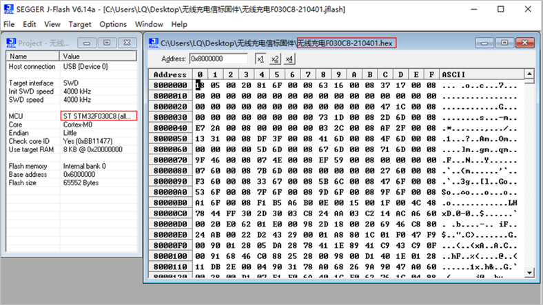
The communication control F030C8.jflash firmware corresponds to STM32F030C8Tb (five pins for firmware burning), and the wireless charging F030K6.jflash firmware corresponds to the XM1008F6p6 chip (four pins for firmware burning). Please verify carefully to avoid burning the wrong firmware.
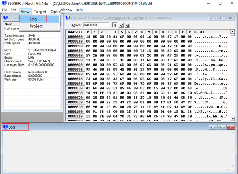
After successfully opening the project, click View->Log to open the bottom burning record box to check if the connection and burning were successful.
8. Starting the Burning Process
Connect the downloader that is already connected to the beacon transmitter to the usb cable and plug it into the computer. Then click Target -> Connect in the J-Flash window to establish a connection. If the connection is successful, it will prompt “Connected successfully“.
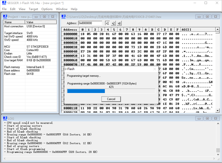
Once connected successfully, click Target -> Production Programming.
Clicking Production Programming or using the shortcut key F7 will display a download progress bar, indicating that the firmware is being burned, as shown:
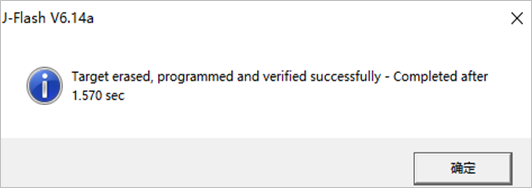
Once the progress bar completes, a pop-up window will appear, indicating that the target erase, programming, and verification were successful, along with the time taken. At this point, click OK to complete the firmware burning operation.
9. Fault Repair Process
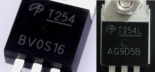
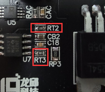
Connect a single beacon light to the digital power supply, setting the output voltage of the digital power supply to 24V. Power on the beacon light; under no load, the digital power supply should generally output 0.15A or less. If it reaches 0.2A, due to differences in parameters from different manufacturers of AOT254L (T254), adjustments may be necessary by modifying the resistors. (If there are no charging anomalies, modifications may not be necessary.)
To modify, you can change RT2 and RT3 resistors to 33Ω (measured with a multimeter when powered off), which will generally prevent TPS28225 from burning out.
The BV prefix T254 corresponds to RT2 and RT3 resistors, which are set to 10Ω by default (measured with a multimeter when powered off), while the AG prefix T254 corresponds to RT2 and RT3 resistors, which are recommended to be changed to 33Ω.
Question: Is it permissible for upright cars to occasionally touch the track?
Response: This is allowed. It is not permissible for upright cars to slide along the track.