In factories, different devices are designed by manufacturers, and there are many types of PLC control systems. The types of sensors used also vary; some use NPN type, while others use PNP type. Therefore, many electricians feel confused when they see NPN and PNP sensors and do not know where to start. Here, I will share the differences between these two types of sensors based on practical experience and how to apply them in real work.
Control Principles of NPN and PNP SensorsPART 01
In our industrial control, sensors can be two-wire, three-wire, or four-wire systems. Among these, the three-wire and four-wire systems have output signal types that can be normally open (NO) or normally closed (NC). The most commonly used are three-wire NPN and PNP output type sensors, which are normally open (NO) sensors. Below, we will take this type as an example.
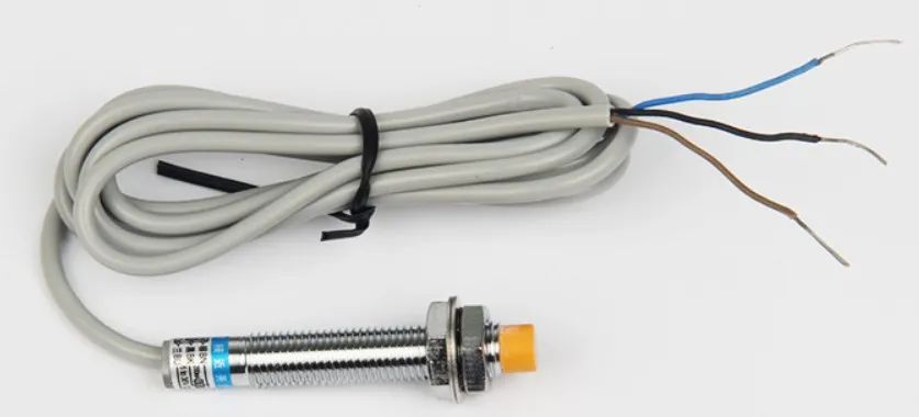
Figure 2 Sensor
The three-wire sensor typically has three wires: the brown wire represents the positive terminal (VCC), the blue wire represents the negative terminal (GND), and the black wire represents the signal output terminal (OUT), as shown in Figure 2. The core control device for both NPN and PNP sensors is a transistor, and their checking and amplification circuits are the same.
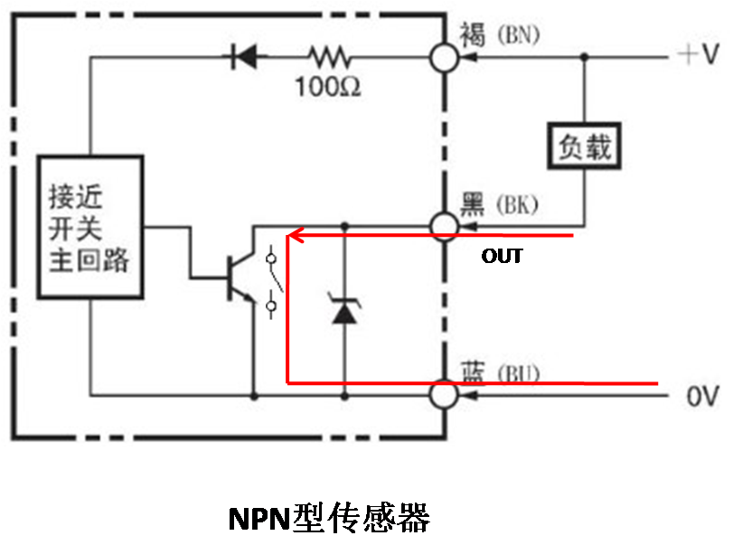
Figure 3 NPN Sensor
The control output device of the NPN sensor is an NPN transistor. When the proximity switch operates, the collector and emitter act as a switch that closes, and the collector open-collector output connects to the negative terminal of the power supply, resulting in a low output level (as shown in Figure 3).
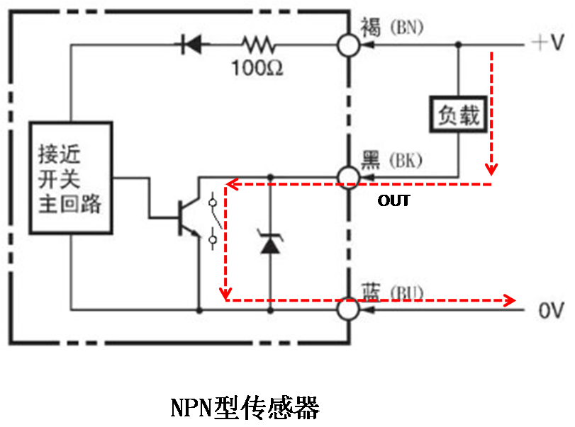
Figure 4 Current Flow Direction of NPN Sensor
When controlling a load, the current flow direction is: 24+——flow into the load——flow out from the load into the sensor OUT terminal——sensor 0V terminal——0V. The current flows from the sensor OUT terminal (as shown in Figure 4).
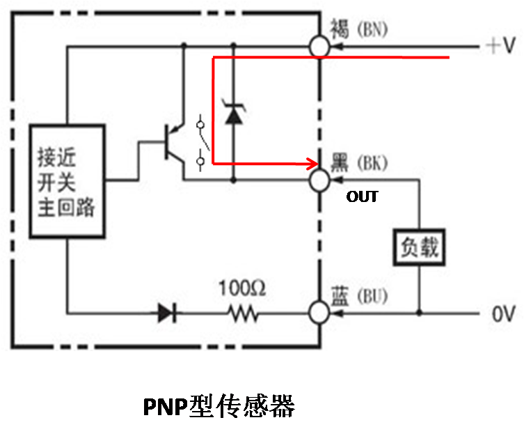
Figure 5 PNP Sensor
The control output device of the PNP sensor is a PNP transistor. When the proximity switch operates, the collector and emitter act as a switch that closes, and the collector open-collector output connects to the positive terminal of the power supply, resulting in a high output level (as shown in Figure 5).
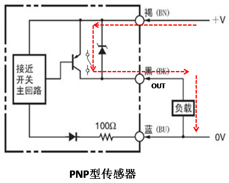
Figure 6 Current Flow Direction of PNP Sensor
When controlling a load, the current flow direction is: 24+——flow out from the sensor OUT terminal——flow into the load——flow out from the load——0V. The current flows out from the sensor OUT terminal (as shown in Figure 6).
Wiring Methods for PLC Digital Input ModulesPART 02
PLC digital input modules have two different wiring methods: sourcing input method and sinking input method. The so-called sourcing and sinking inputs are relative to the PLC input common terminal (COM or M terminal). When connecting, you need to choose the corresponding sensor based on different logic.
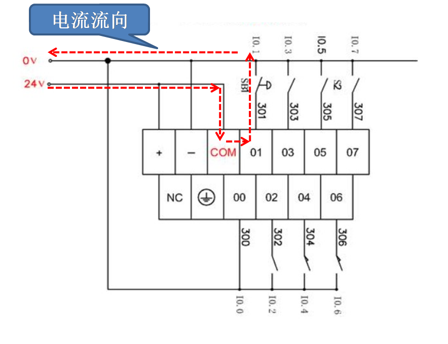
Figure 7 PLC Sourcing Input
When the current flows into the module from the common terminal and flows out from the module’s input channel, this wiring method is called sourcing input, with the positive terminal of the power supply as the common terminal for sourcing input (as shown in Figure 7).
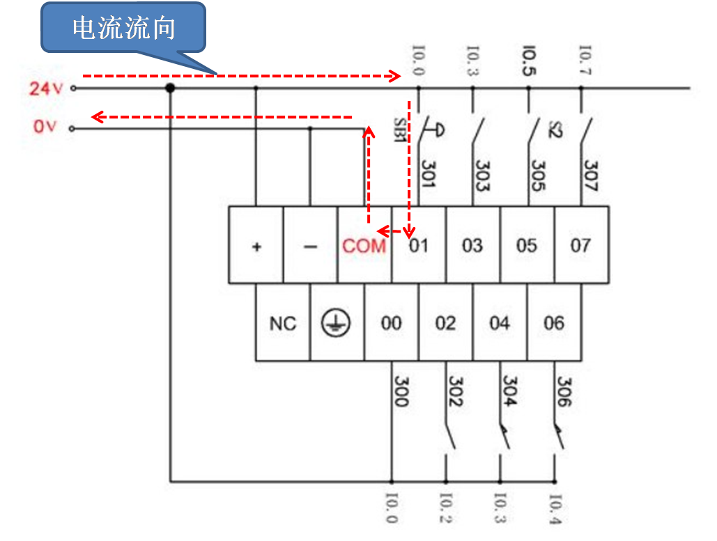
Figure 8 PLC Sinking Input
When the current passes through an external switch, flows into the module’s channel, and then flows out from the common terminal through the internal circuit, this wiring method is called sinking input, with the negative terminal of the power supply as the common terminal for sinking input (as shown in Figure 8).
Connecting NPN and PNP Sensors to PLCPART 03
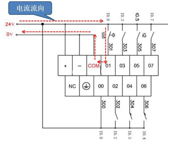
Figure 9 NPN Sensor Wiring with PLC
Based on the analysis above, when the output signal of the NPN sensor is connected to the input terminal of the PLC, the common terminal M of the PLC must be connected to a high level (i.e., the 24V power supply). At this time, the PLC input connection should use the sourcing method (as shown in Figure 9).
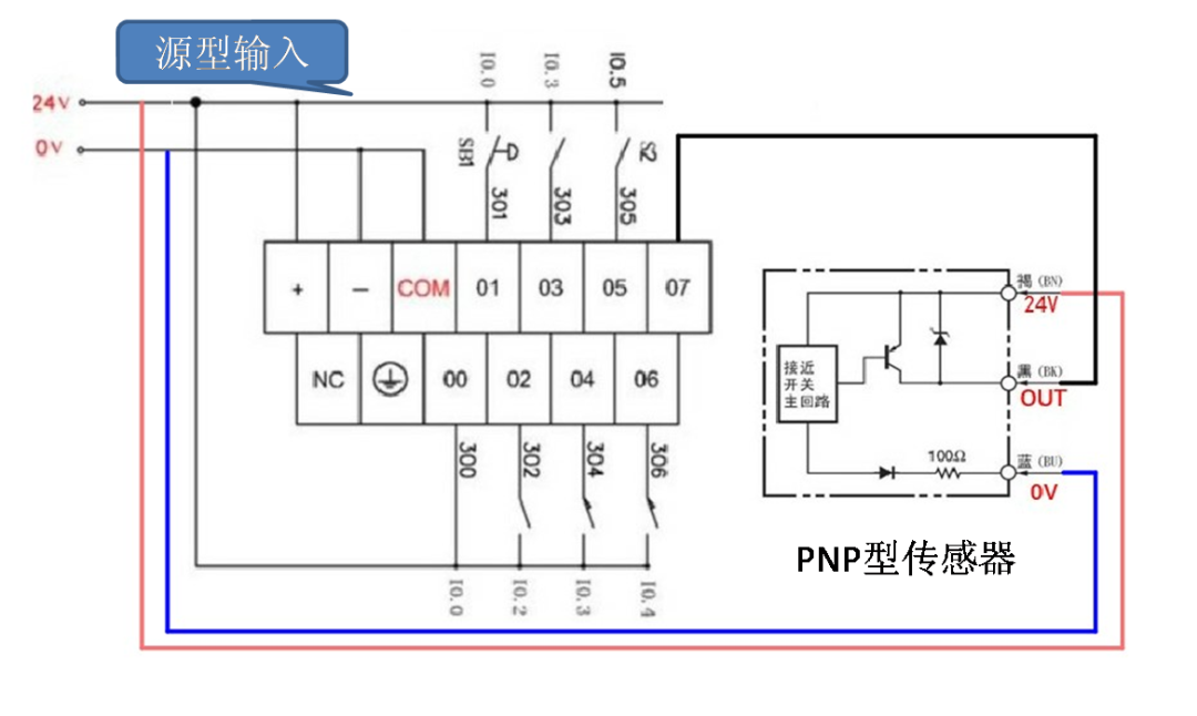
Figure 10 PNP Sensor Wiring with PLC
For PNP output sensors connected to the PLC input signal terminal, the common terminal M must be connected to a low level (i.e., the 0V power supply). At this time, the PLC input connection should be made using the sinking method (as shown in Figure 10).
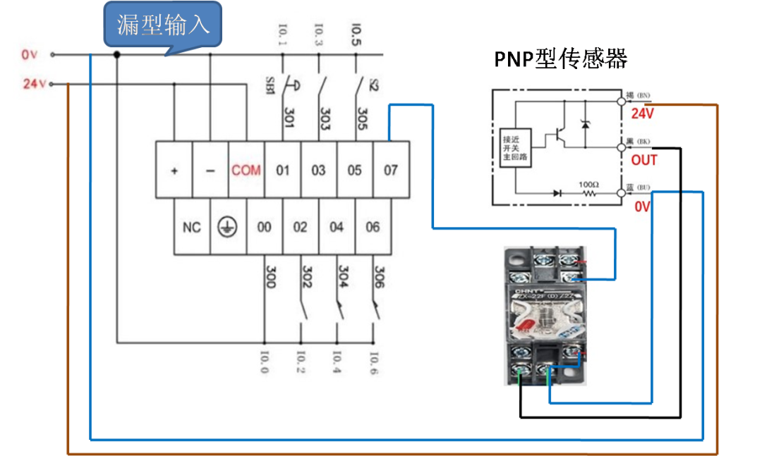
Figure 11
Of course, there is also a situation in practice where if your PLC input terminal is set up for sinking or sourcing, and you do not have the corresponding PNP or NPN sensors on hand, you can use an intermediate relay to convert the sensor output signal to meet the correct PLC input signal (as shown in Figure 11). However, this method is less effective compared to directly connecting the sensor to the PLC and is only suitable for emergency use. It should not be used in high-precision applications.
Disclaimer: This article is reproduced from the internet, and the copyright belongs to the original author. If there are any copyright issues, please contact us for deletion. Thank you!