
Hello everyone, I am “Uncle”, today we will talk about how Siemens PLC and automation control can make factories smarter. PLC (Programmable Logic Controller) has become an indispensable part of modern industry, as it can improve production efficiency, reduce human errors, and optimize resource management through automation control. Whether you are a beginner just getting into automation or an experienced engineer, this article will provide you with practical techniques and application examples to help you better understand and utilize PLC.
First, let’s briefly discuss the basic concept of PLC. The PLC acts like the “brain” of the factory, responsible for receiving signals from various sensors and then controlling actuators (such as motors, cylinders, etc.) to perform corresponding operations based on these signals. Its working method is similar to pressing a remote control button to control the TV; the PLC decides what output signal (such as turning on the TV) to send based on the input signal (such as a button press).
Siemens PLC is a very popular model on the market, known for its powerful functions and wide range of applications, from small businesses to large production lines. The Siemens PLC mainly consists of a CPU, input/output modules (I/O), and a power supply module. The CPU is responsible for processing instructions, while the I/O modules receive external signals and transmit them to the PLC or send the PLC’s output signals to external devices.
In automation systems, the input and output terminals of the PLC are key components. The input terminals of the PLC receive signals from sensors, such as temperature sensors and photoelectric switches; while the output terminals control the start or stop of devices, such as starting motors or opening valves.
Let’s take a look at the common input and output connection methods for Siemens PLC:
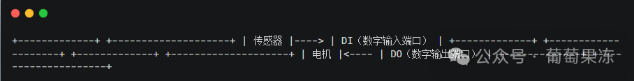
In this wiring diagram, sensors transmit information to the PLC through digital input ports (DI), while the PLC controls the start or stop of the motor via digital output ports (DO).
Programming for Siemens PLC is usually done using Ladder Diagram, which is structurally very similar to circuit diagrams and is easy to understand and operate. Below is a simple ladder diagram example used to control the start and stop of a motor:
I1: Input port, connected to the sensor’s signal, indicating the status of the sensor.
Q1: Output port, connected to the motor controller, used to start or stop the motor.
The logic of this program is very simple; when the sensor (I1) detects an object passing, the PLC will output a signal to control the motor (Q1) to start. You can write and debug this program using Siemens TIA Portal and other software.
Let’s look at a specific application case: suppose you need to use PLC to control the start and stop of multiple motors on a production line for automated material handling. By using Siemens PLC, you can set multiple sensors to detect the state of materials (such as whether the material has reached a designated position) and control the start and stop of motors based on these input signals.
Sensor S1 detects that the material has reached the starting point of the production line, and the PLC starts motor M1 to begin transporting the material.
Sensor S2 detects that the material has reached the end of the production line, and the PLC starts motor M2 to transport the material to the next workstation.
In this way, the PLC helps achieve automated control of the production line, improving efficiency and reducing human intervention.
Common Problems and Solutions
Unstable input signals causing abnormal device startup
Solution: Check if the input terminal connections are stable and ensure the wiring is secure. If the signals are subject to interference, anti-interference circuits can be added to ensure accurate signal transmission.
Solution: Check the working voltage of the sensor and the compatibility with the PLC input port. If the voltage does not match, a signal converter may be needed. Also, ensure that the sensor is correctly installed and that there are no loose connections.
Solution: First, confirm whether the program logic is correct, and then check if the PLC’s power supply is normal. If there is an issue with the PLC program, it can be debugged in advance using the simulation function of TIA Portal to avoid problems during on-site debugging.
When wiring, be sure to confirm that terminal markings are clear to avoid miswiring that could cause short circuits or damage to equipment.
During debugging, never arbitrarily adjust the PLC’s power supply voltage, and ensure the voltage range is within the PLC’s requirements.
For controlling high-voltage equipment, always implement electrical safety measures to prevent electric shock accidents.
In the beginner stage, you can start from simple switch control programs and gradually understand the basic functions of PLC.
By doing actual wiring and debugging, you can accumulate experience, especially with problems encountered during debugging, which can deepen your understanding of PLC control principles.
Utilize the simulation function of the PLC often; it can help you debug programs without actual hardware, reducing the risk of hardware damage.
Through this article, you should have a preliminary understanding of the basic operations and application scenarios of Siemens PLC. PLC is an indispensable tool in industrial automation; it not only improves production efficiency but also ensures the efficient operation of factories. If you have any questions or want to further explore other functions of PLC, please leave a message below.