Today, I will present an example of interference from a variable frequency drive (VFD) on a PLC’s analog signal and a solution using a signal isolation module to overcome such interference.
1. Example 1: Phenomenon Description
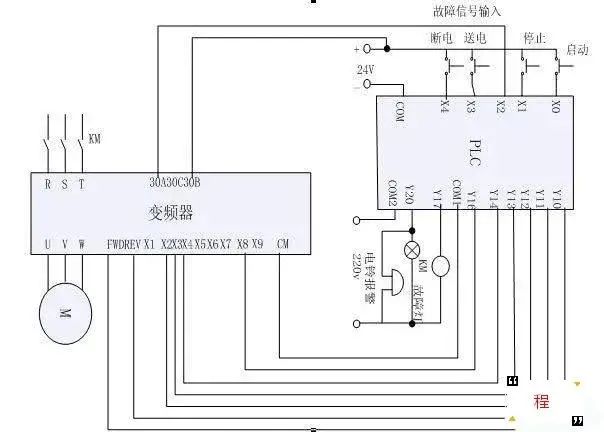
In a Siemens PLC, the AO point outputs a 4-20mA current control signal to a Siemens VFD, but it cannot control the VFD to start.
Troubleshooting
1. Suspected issue with the analog output board; measured the 4-20mA output signal with a multimeter, and the signal is normal!
2. Initially suspected a problem with the control signal input of the VFD; replaced it with another VFD of the same model, but the issue persisted.
3. Used a handheld signal generator to provide a 4-20mA output signal to the VFD, and it started normally, thus ruling out faults in the analog output board and the VFD.
4. It was inferred that the interference signal from the VFD was transmitted to the analog channel.
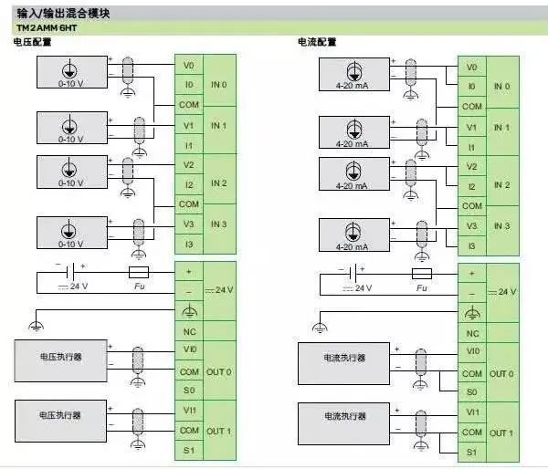
5. To verify, a signal isolation module TA3012 was installed in the PLC’s 4-20mA output channel; terminals 5 and 6 were connected to the analog output module, terminals 1 and 2 to the VFD, and terminals 3 and 4 to an external 24VDC power supply, allowing the VFD to start normally.
6. It was concluded that the root cause of the problem was the interference from the VFD affecting the analog channel.
Precautions
In a control system where PLCs and VFDs are used simultaneously, the following precautions should be emphasized:
1. The power supply for the PLC and the power supply for the drive system (VFD power supply) should be separately configured, and the PLC’s power supply should use an isolation transformer;
2. Power lines should be kept separate from signal lines, and signal lines should be shielded;
3. Whether for analog signal input or output, all analog channels should use signal isolation modules;
4. Implement software filtering design in the PLC program;
5. Design the signal ground and power ground separately.
2. Example 2
“In the workshop, there are 10 units of 250KW motors, with loads being high-pressure pumps. The VFD uses Schneider ATV71 connected to the PLC via DP, with the PLC being Siemens 300, and the pressure transmitter is Siemens, with a 4-20mA analog signal input to the PLC using shielded wire.
After debugging, everything ran normally for a week. After the manufacturer left, suddenly the 8th pump, set to 40 kg pressure, showed an actual value of 70 kg. When set to 80 kg pressure, the actual value was 110 kg. Initially suspected a sensor fault, but replacing it with another pump worked fine. Then, with all VFDs running, pumps 3, 4, 5, 6, 7, 9, and 10 also exhibited similar issues.
It was speculated that the pressure sensor was affected by interference from the VFD. The manufacturer suggested adding a metal pipe shield. However, considering the difficulty of on-site construction (the control room is over 30 meters away from the motor, with all underground cable trenches), it was believed that the harmonic interference from the VFD should cause fluctuations in pressure values, and it is rare to see interference causing a linear increase. Initially suspected a problem with the manufacturer’s program, as the display showed a pressure value of 40 kg, but the VFD output was 70 kg frequency. The manufacturer disagreed, stating they used Siemens standard PID blocks.
It was puzzling. I accidentally discovered that the negative terminal of the manufacturer’s sensor was connected to the M terminal of the PLC analog input along with the shield. After removing the shield wire and connecting it to the equipment ground, the fault was eliminated.
Speculation: For a 2-wire sensor, the positive terminal receives 24V voltage from the PLC, while the negative terminal is where the sensor outputs the 4-20mA current. When the shield wire was connected to the negative terminal, the induced electromotive force on the shield wire generated a current that entered the PLC input, causing an additive current, which resulted in a linear increase in pressure values. After running for just two days, the same situation occurred again, and more seriously, one of the pressure sensors still showed 40 kg pressure even after being removed. Ultimately, it was found that the negative terminal on the PLC input side had been stripped too long, causing a short circuit between channels and resulting in signal cross-talk.
This reminded me that during the initial debugging, the manufacturer asked if the equipment ground and cabinet ground were not on the same ground. After grounding both ends of the pressure sensor shield wire, the interference was particularly severe, making it impossible to display. I casually mentioned that it was grounded at one end. They said it was fine. Now I realize that initially, the current output side of each sensor was connected together through the shield wire, causing a short circuit, and after removing the ground wire from the sensor side, the signals returned to normal because the shield wire was no longer connected together.
Disclaimer:This article is a network reprint, and the copyright belongs to the original author.The articles reproduced do not represent the views of this public account or its authenticity.However, due to the large number of reproductions, it is impossible to confirm the true original author. If there are copyright issues, please contact us in a timely manner, and we will delete the content to protect your rights!
If you like it, please give it a thumbs up and take a look