 Search on WeChat
 Technical TrainingWhat is PLC?
Learn about PLC through the following three parts:The concept of PLC, what PLC can do, and how to wire PLC.
Concept of PLC / Part 1.
PLC (Programmable Logic Controller) means: Programmable Logic Controller.
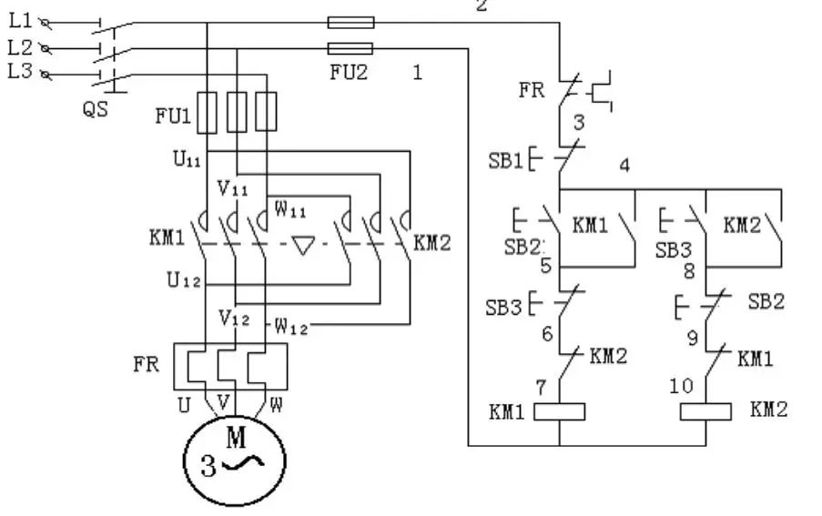
Before the advent of PLC, traditional circuits were like this (as shown in the figure below).
By pressing the normally open contact of button SB2, the KM1 AC contactor coil is energized, closing the main contact of the AC contactor KM1, allowing the three-phase asynchronous motor to operate in the forward direction. The normally open contact of SB3 controls the motor’s reverse operation.
From the circuit diagram, it can be seen that the functions of traditional circuits are fixed, and the contacts are limited. If you want to modify the circuit function, it requires extensive rewiring. If you need to control multiple motors, you have to connect many corresponding lines. Moreover, troubleshooting on-site when a fault occurs is very troublesome.
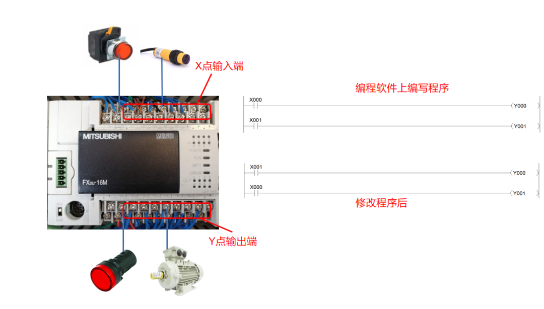
After using PLC, connecting these components becomes very simple and easy (as shown in the figure below).
Just connect suitable components like switches to the PLC input, and loads like indicator lights to the output.
Then, write the program shown in the figure below in the programming software, upload it to the PLC for execution. By pressing the external switch connected to the PLC, the PLC scans the program, the X000 normally open contact closes, controlling the Y000 coil to energize, and the corresponding Y point outside the PLC can output control loads.
Advantages of PLC:
If the external button X00 controls Y001, you only need to modify the program. Re-upload it to the PLC for execution without rewiring; pressing the X00 button can control different loads.
You can write some logic programs in the programming software.
Moreover, there is no limit to the number of normally open and normally closed contacts used in the programming software.
You can also monitor the program through the programming software to observe the actual situation, which is quick and intuitive, making troubleshooting very easy.
From the above, do you have a certain understanding of the editable logic controller PLC?
What Can PLC Do / Part 2.
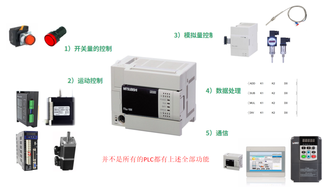
In addition to connecting common switches and controlling discrete signals, what else can PLC control? Here are five categories summarized (as shown in the figure below).
(1) Control of Discrete Signals
For example, connecting a switch button to the PLC input and writing a program to control loads like indicator lights.
(2) Motion Control
PLC can send high-frequency pulses through high-speed pulse output points to drive stepper and servo drives.
(3) Analog Control
Temperature sensors can sense temperature, and the data can be sent to the PLC for processing, allowing the control of loads to perform corresponding actions. PID control can also be implemented for constant pressure water supply, etc.
(4) Data Processing
PLC has functions for mathematical operations, conversions, and sorting, enabling data collection, analysis, and processing. For example, setting the number of cycles for action processes. Programs can also be written to implement calling functions in restaurants and banks, etc.
(5) Communication
In many automation devices, touch screens can be seen, where various components and pages can be designed, and communication can be established with the PLC through communication lines. Buttons can be created on the touch screen to replace physical buttons. Numeric components can display data from the PLC, and images can represent the working status of various components.
How to Wire PLC / Part 3.
Before understanding how to wire the PLC input and output terminals, let’s look at what components can be connected to the PLC input and the three essential elements of a basic circuit (as shown in the figure below). They are generally divided into two-wire and three-wire types.
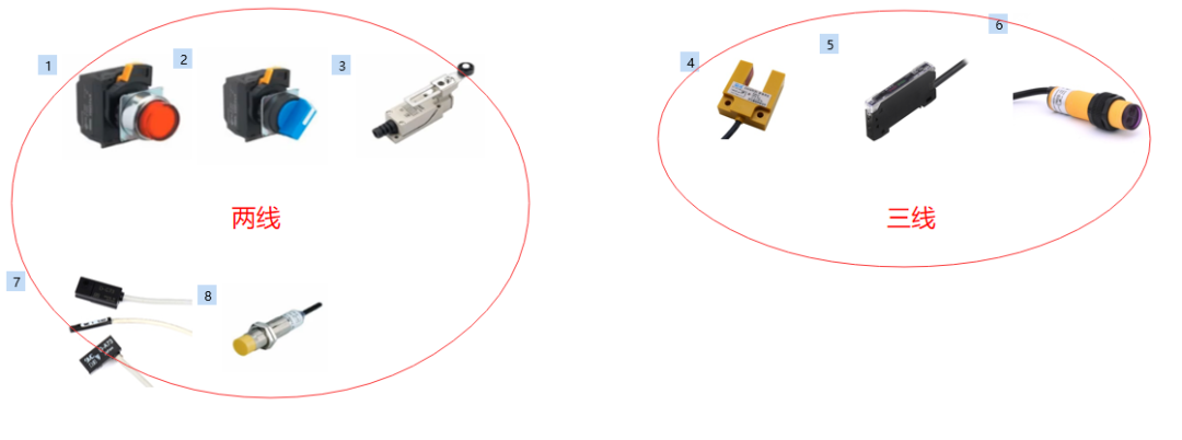
Input Components:
① Push Button Switch
② Rotary Switch
③ Limit Switch
④ U-shaped Switch
⑤ Fiber Amplifier
⑥ Photoelectric Switch
⑦ Magnetic Switch
⑧ Proximity Switch
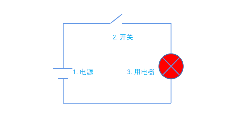
Three Essential Elements of a Basic Circuit:
A basic circuit requires these three elements:
① Power Supply
② Switch
③ Load
After understanding what components can be connected to the input terminal and the three essential elements of a circuit, let’s explain how to connect these components to the input terminal of the Mitsubishi FX3U PLC using a power supply (generally a 24V power supply, specific details refer to the manual) (as shown in the figure below).
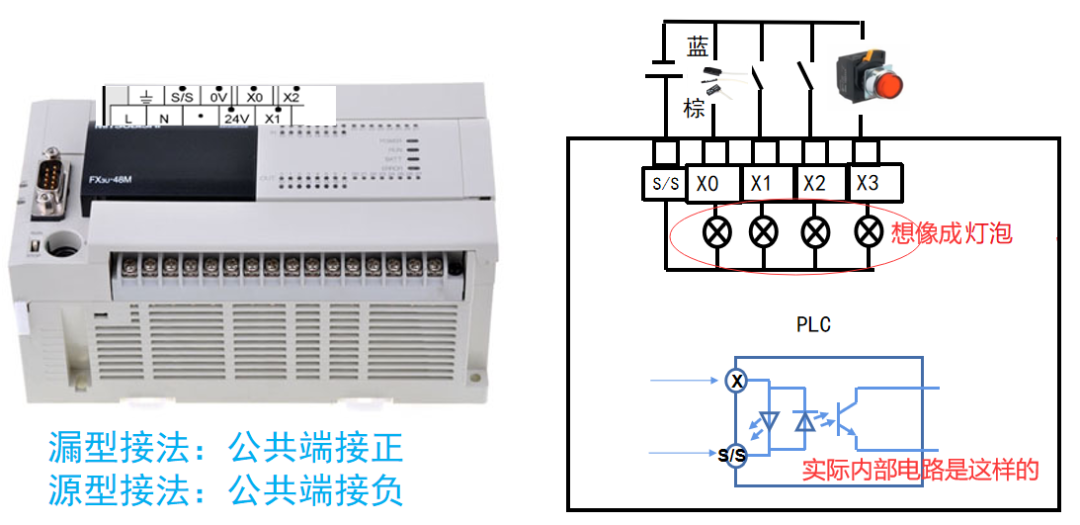
Two-Wire Connection Method:
① First, consider each X point input terminal as a small light bulb for easier understanding. All ends of the light bulbs are connected to the S/S common terminal.
② Then connect one end of the push button switch to the X3 input terminal (and it can be connected to the same common terminal for all X points), and the other end to the negative terminal of the external power supply.
③ Finally, connect the positive terminal of the external power supply to the S/S terminal.
Analyzing this, the power flows from the positive terminal to S/S, through the light bulb, and then through the switch back to the negative terminal of the power supply.
The two-wire switch connection is that simple. However, it is important to note that magnetic switches have brown and blue wires, with brown being positive and blue being negative. (When wiring, pay attention to the direction of the power current; the power flows from the positive terminal to S/S and then through the X point, with the brown wire connected to the X terminal and the blue wire connected to the negative terminal.)
Additionally, connecting the PLC common terminal S/S to the positive terminal of the power supply is called a sinking connection, while connecting it to the negative terminal is called a sourcing connection. (When the common terminal S/S is connected to the negative voltage, the blue wire of the magnetic switch connects to the X point, and the brown wire connects to the positive voltage.)
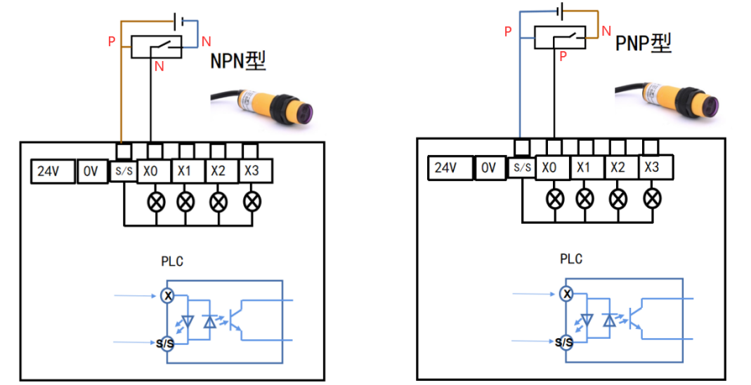
Three-Wire Connection Method:
Photoelectric Switch Description: Three-wire photoelectric switches are divided into NPN and PNP types. (They look the same; refer to the manual or nameplate for distinction.) N indicates low level, and P indicates high level.
The three wires are brown, blue, and black, with brown being positive, blue being negative, and black being the signal.
First, connect the brown and blue wires of the photoelectric switch to the positive and negative terminals of the power supply, respectively; then connect the black signal wire to the PLC input X point; finally, if it is an NPN type, connect the S/S common terminal to the positive terminal, and if it is a PNP type, connect the S/S common terminal to the negative terminal.
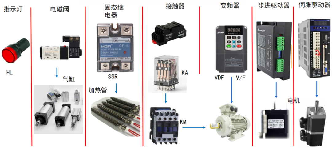
Output Components:
① Indicator Light
② Solenoid Valve Control Cylinder
③ Solid State Relay Control Heating Element
④ Intermediate Relay
⑤ Frequency Converter
⑥ Stepper Driver
⑦ Servo Driver (as shown in the figure below)
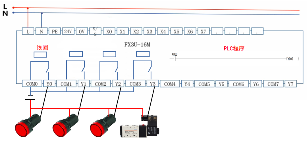
▲ Output Wiring
For easier understanding, the following wiring explanation is provided: The output terminal of a relay output type PLC internally consists of a coil. When the program X000 normally open contact closes, the Y000 coil is energized, and the corresponding Y000 coil is powered, causing the normally open contact of Y000 to close, energizing the external load circuit. The external wiring of the PLC is shown in the figure below.
Transistor output types are divided into sourcing and sinking:
Sinking: COM port connected to the negative terminal of the power supply;
Sourcing: COM port connected to the positive terminal of the power supply.
Relay and thyristor outputs do not distinguish between positive and negative terminals of the power supply.
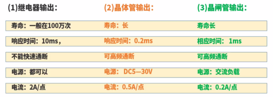
Summary of Three Output Types (as shown in the figure below): There are transistor type (MT), relay type (MR), and thyristor type (MS).
Supplement:
① When the system output frequency is below 6 times per minute, relay output PLC should be preferred due to its simple circuit design, strong anti-interference, and load-bearing capacity. (When the frequency exceeds 6 times per minute, it is advisable not to choose relay output PLC, as the output frequency is too fast, exceeding its lifespan of 1 million times will lead to failure.)
② When controlling stepper or servo motors, choose transistor output PLC, as it has high-speed pulse output points that can quickly turn signals on and off.
Through the three parts explained in this article, do you have a certain understanding of PLC? If this article has helped you, please follow and like it. Thank you for your support.
HISTORY/Previous Recommendations
Complete question bank for the 2021 Electrician Beginner Exam (including answers)
Is troubleshooting frequency converters difficult? Just one click!
Can you sweep through all electrical exam questions with one click? Do you not have this tool yet?
Which of the five major electrical drawing software (CAD, Eplan, CADe_simu…) do you pick?
Latest electrical version CAD drawing software, with super detailed installation tutorial!
Latest electrical drawing software EPLAN, with super detailed installation tutorial!
Common issues for beginners using S7-200 SMART programming software (with download link)
Comprehensive electrical calculation EXCEL spreadsheet, automatically generated! No need to ask for electrical calculations!
Bluetooth headsets, electrician/PLC introductory books are freely given away? Come and claim your electrical gifts!
Basic skills in PLC programming: Ladder diagrams and control circuits (with 1164 practical cases of Mitsubishi PLC)
Still can’t understand electrical diagrams? Basic electrical diagram reading skills and simulation software for quick hands-on practice!
12 free electrician video courses, 10GB software/e-book materials, and 30 days of free electrician live classes are being given away!
Don’t forget to like and share! 
 Click “Read the Original” to learn PLC/electrician courses for free.