DIYer: Smiling Duck
Production Time: Half a Day
Difficulty Level: ★★☆☆☆
GEEK Index: ★★★☆☆
Are you still using a universal board for repairs? Are you struggling to create the circuit and layout you want with a universal board? For many electronic enthusiasts today, a universal board can no longer meet the production needs, but having a manufacturer make PCB samples is not cost-effective, costing dozens of yuan for a single board… So is there no solution? Not so fast, here comes the photosensitive board! It is inexpensive, easy to make, can easily build complex circuits including surface mount circuits, has high precision, and overall, it is convenient and practical, which are the advantages of photosensitive circuit boards!
Today, I will demonstrate the simplest parallel circuit with 20 “grass hat” LEDs, teaching everyone how to fully utilize the advantages of the photosensitive board – my circuit is neater, more convenient, and better to use than yours!
Steps:
-
1. Materials and Tools
-
2. Draw and Print Your Circuit Diagram!
-
3. Start Photosensitization!
-
4. Prepare the Developer and Develop!
-
5. Start Etching!
-
6. Drill Holes, Install Components, Solder, and You’re Done!
-
7. DIYer Sign-in Area
1. Materials and Tools
○ 1 Photosensitive Circuit Board
○ 1 Bottle of Ferric Chloride or 1 Pack of Eco-friendly Etching Agent
○ 1 Pack of Photosensitive Developer
○ 1 Roll of Transparent Tape
○ 1 Pencil
● 1 Desk Lamp
● 1 Glass Sheet (the thicker, the better)
● 1 Plastic Basin or Fresh-keeping Box (make sure it’s plastic!)
● 1 Utility Knife
● 1 Steel Ruler
● 1 Electronic Scale or Balance (unless you want to use all the chemicals at once)
● 1 Stopwatch, Watch, Clock, anything that can time
● 1 Flat Tweezers
● 1 Electric Drill, Bench Drill, anything that can drill holes. Make sure to use a fine drill bit! About 0.8mm is suitable.
2. Draw and Print Your Circuit Diagram!

First of all, you need to draw the circuit diagram. Here, I use a PCB design software called Sprint Layout. As for what software you use, I can’t control that…
However, I still recommend Sprint Layout to all the novice friends! It has gained countless fans among beginners for its simple operation and ease of use!
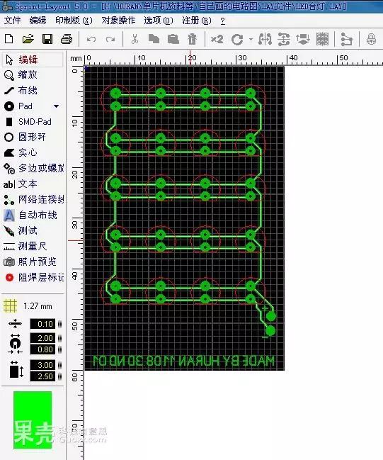
Draw the circuit diagram.
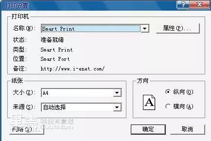
By the way, this Sprint Layout needs to be printed… If you have a printer at home, then I have nothing to say. If you don’t have a printer, go search for “Smart Printer Virtual Printer Cracked Version” on Baidu, it’s a very practical green software (of course, you need to crack it), it can convert any document with a print option into many formats of images, then take these images to a printing shop. This saves you from the awkward situation of bringing a .LAY file to print, and they can’t open it…
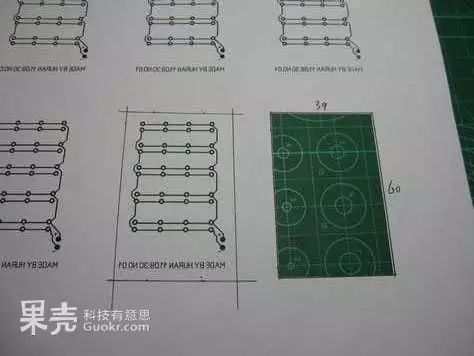 Alright, now you have printed out the circuit diagram! (Use regular A4 paper, the lighter the better) Cut it down to the size you designed! Be careful with your fingers!
It is important to note that you should carefully observe the printed circuit; sometimes there may be broken lines or short circuits… That’s right, any flaw will be mirrored on the photosensitive board. So, if you are using an inkjet printer, please widen the line spacing a bit; if there are broken lines, fix them, and if there are short circuits, adjust the line spacing wider and reprint! If you have an excellent laser printer, just ignore this paragraph…
3. Start Photosensitization!
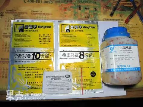 In the middle is an old version of the photosensitive board from Golden Electronics (already expired TwT), on the left is the new version of the photosensitive board. The far right is a bottle of ferric chloride. Below is the photosensitive developer.
Many people ask about the price of the photosensitive board; in Guangzhou, where I live, you can buy a large board of 100×150mm for 10 yuan at a store on the third floor of Gangding New Saige Electronics City, which is quite sufficient.
A bottle of ferric chloride is around a dozen yuan and can etch many circuit boards. The developer costs about 1 yuan…
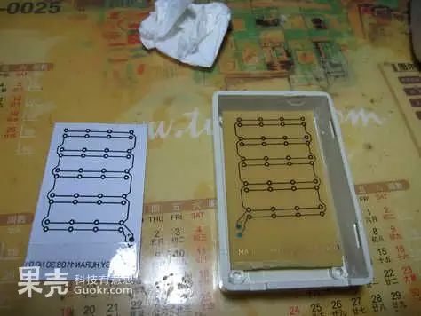
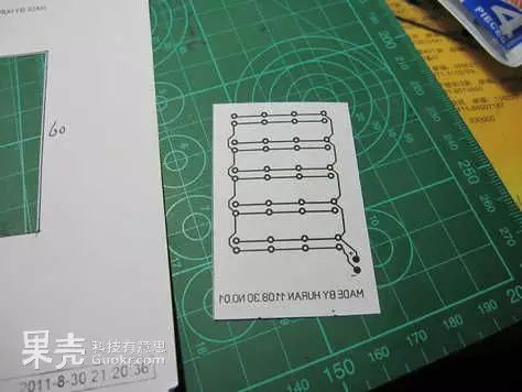 The cut circuit diagram.
Note: Due to the photosensitive board’s sensitivity to light, I turned off the desk lamp; there was no way…
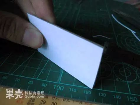
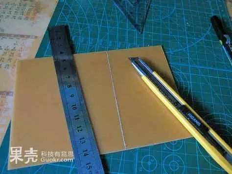 Use a utility knife and steel ruler to mark the area you need on the photosensitive board. Make several cuts and apply more force!
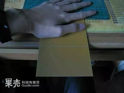 Place the circuit board as shown in the picture, then press down with the other hand! Use force! “Snap!” Done, the cutting is complete!
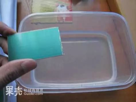
 Unfortunately, the cut is not neat; the root cause is still that I didn’t use enough force to cut the board (you can try using a glass cutter)..
 Alright, recut, and it’s done. Remember to peel off the white protective film! Then proceed with the photosensitization!
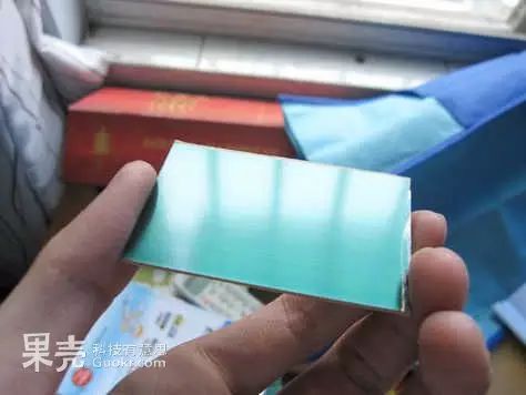
 The effect after peeling off the photosensitive film; you should see the dark green photosensitive layer.
Stick the side of the circuit diagram with writing onto the photosensitive film using transparent tape.
 With the photosensitive film facing up, press down with a glass sheet. The glass was repurposed from someone else’s renovation… The thicker, the better; thick means heavy, which presses tightly.
Control the distance between the desk lamp and the board to about 5CM!
Alright, start the photosensitization! Be careful not to touch the glass during the photosensitization process, do not turn off the desk lamp or move its position. After about 20 minutes, come back to turn off the desk lamp!
4. Prepare the Developer and Develop!
While waiting for the photosensitization, let’s prepare the developer.
One pack of developer contains 29G; more than enough, about 10G is sufficient… Mix the developer with water in a ratio of 1:20 (emphasizing again, be sure to use a plastic basin!).
Pour the developer into the prepared 200ML of water, stir, and shake the container until the developer is completely dissolved, with no granules left.
 Take out the photosensitive board; peel off the transparent tape, it should look like this…
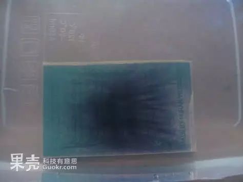 Gently place the board into the developing solution (don’t throw it in, dear!), after a few seconds you will see the non-circuit part of the photosensitive film gradually turning into green smoke and floating away. At this point, gently shake the plastic basin until the situation resembles the following image.
The circuit part should be clear, and the non-circuit part of the dark green photosensitive film should be completely dissolved. Wait another 3-5 seconds to ensure the imaging process is 100% complete!
Note: Used developing solution is strictly prohibited from reuse. Please dilute the used developing solution 20 times before discharging it into the municipal sewage system!
The board should look very nice now, hee hee.
5. Start Etching!
Measure out an appropriate amount of ferric chloride, and prepare the etching solution in a ratio of about 3:1 of ferric chloride to water.
Note: Ferric chloride is corrosive; do not touch it directly with your hands. Tweezers used to pick it up should also be cleaned immediately after use. If it accidentally gets into your eyes, wash them with plenty of water and seek medical help as soon as possible!
Throw the ferric chloride into the water, and check back in a few minutes; it dissolves very slowly…
When the solution is brown and has no solids in it, it means the etching solution is ready!
Note: Make sure there are no impurities in the etching solution! The most intolerable impurity in the etching solution is grease! So if you just finished eating chips, please wash your hands before starting!
Putting a few iron nails in the water can speed up the etching process, or so it is said. It doesn’t affect the usage, so why not give it a try?
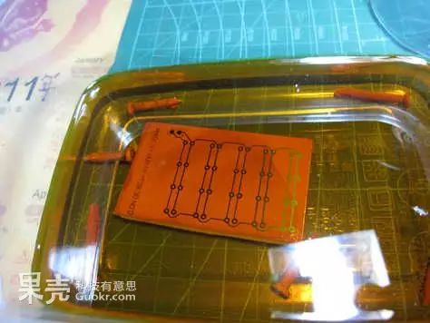
Gently place the well-photosensitized board into the etching solution (it should actually float on the surface with the circuit facing down, but due to the board’s size, it can only sink to the bottom…)
Be careful not to move the basin during the process, and do not touch the board with anything! Otherwise, you will bear the consequences!
 After an hour, check it (if you find it too long, increase the concentration of the etching solution!). At this point, you can use a plastic bag as gloves to carefully take out the board (be careful not to touch the circuit part!). Check if the non-circuit part no longer has a metallic color? If there is still some, continue soaking for another half an hour and check again. If you are unsure, you can measure the resistance of the non-circuit part with a multimeter; the resistance should be infinite!
If you measure something like this, then congratulations, your first photosensitive circuit board has been successfully made!
6. Drill Holes, Install Components, Solder, and You’re Done!
Time for the bench drill to come out, let’s drill! Be careful not to drill off-center!
Dense holes… It’s best to clean up the debris from the drilling…
Alright, let’s show off the modified bench drill… The highlight is the added lighting system (just 6 3MM LEDs), enhancing the structural stability.
Install the components, solder! Place the 20 “grass hat LEDs” properly.
I’m soldering and soldering…
PS: The legs of the cut components…
Alright, your first beautiful printed circuit board has been successfully made, let’s celebrate!
This article is excerpted from: Guokr (Scientific People WeChat public account: scientific_guokr)
Does not represent the views of the China Power Supply Society, and secondary reproduction is prohibited. For reprints, please contact the source media.