
Definition of High-Frequency PCB
High-frequency boards refer to special circuit boards with electromagnetic frequencies that are relatively high, used in the fields of high frequency (frequency greater than 300MHz or wavelength less than 1 meter) and microwave (frequency greater than 3GHz or wavelength less than 0.1 meter) PCBs. They are produced using standard rigid circuit board manufacturing methods on microwave substrate copper-clad laminates or through special processing methods. Generally, high-frequency boards can be defined as circuit boards with frequencies above 1GHz.
With the rapid development of science and technology, more and more device designs are in the microwave band (>1GHz) or even in the millimeter-wave field (77GHz) applications (for example, the currently popular 77GHz millimeter-wave antennas for vehicles). This also means that the frequency is getting higher, and the requirements for the substrate of the circuit board are becoming increasingly stringent. For instance, substrate materials need to have excellent electrical properties, good chemical stability, and minimal loss as the power signal frequency increases, highlighting the importance of high-frequency materials.
Classification of High-Frequency PCB Materials
01
By Material
a. Organic materials: Phenolic resin, fiberglass/epoxy resin, Polyimide, BT/Epoxy, etc.
b. Inorganic materials: Aluminum, Copper-invar-copper, ceramic, etc. Mainly chosen for their heat dissipation capabilities.
02
By Finished Product Type
a. Rigid PCB.
b. Flexible PCB.
c. Rigid-Flex PCB.
03
By Structure
a. Single-sided board.
b. Double-sided board.
c. Multi-layer board.
04
By Application
Communication/Consumer electronics/Military/Computers/Semiconductors/Electrical measurement boards…
Common High-Speed Board Materials (Manufacturers)
Welcome to reply with additions.
01
Rogers
RO4003, RO3003, RO4350, RO5880, etc.
RO3000 Series: Ceramic-filled PTFE circuit materials, models include: RO3003, RO3006, RO3010, RO3035 high-frequency laminates.
RT6000 Series: Ceramic-filled PTFE circuit materials designed for electronic circuits and microwave circuits requiring high dielectric constants, models include: RT6006 dielectric constant 6.15, RT6010 dielectric constant 10.2.
TMM Series: Composite materials based on ceramics, hydrocarbons, and thermosetting polymers, models: TMM3, TMM4, TMM6, TMM10, TMM10i, TMM13i, etc.
02
Taconic
TLX series, TLY series, etc.
03
Panasonic
Megtron4, Megtron6, etc.
04
Isola
FR408HR, IS620, IS680, etc.
05
Nelco
N4000-13, N4000-13EPSI, etc.
06
TUC
Tuc862, 872SLK, 883, 933, etc.
Dongguan Shengyi, Taizhou Wangling, Taixing Microwave, Changzhou Zhongying, etc.
Of course, there are many other high-frequency materials not listed here. Among them, Arlon (acquired by Rogers, also an old brand of RF microwave board manufacturers).
Key Indicators for Selecting High-Frequency High-Speed PCB Materials
When selecting substrates for high-frequency circuits, special attention should be paid to the material’s DK and its variation characteristics at different frequencies. For requirements focusing on high-speed signal transmission or characteristic impedance control, the emphasis should be on DF and its performance under frequency, temperature, and humidity conditions.
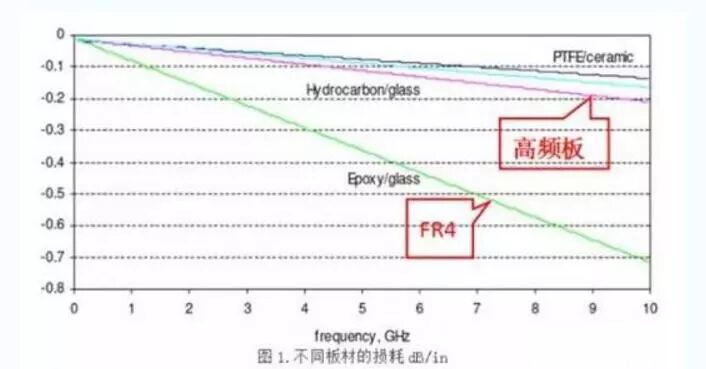
General substrate materials exhibit significant variations in DK and DF values under changing frequency conditions. Particularly within the frequency range of 1 MHz to 1 GHz, the changes in DK and DF values are more pronounced. For example, a general epoxy resin and fiberglass-based substrate material (general FR-4) has a DK value of 4.7 at 1 MHz, while at 1 GHz, the DK value changes to 4.19. Above 1 GHz, the trend of DK value changes becomes more stable. The trend is that as the frequency increases, the DK value decreases (but the change is not large); for instance, at 10 GHz, the DK value of general FR-4 is 4.15. Substrate materials with high-speed and high-frequency characteristics exhibit minimal DK value changes under frequency variations, maintaining a change range of about 0.02 from 1 MHz to 1 GHz. The DK value shows a slight downward trend under different frequency conditions from low to high.
The dielectric loss factor (DF) of general substrate materials is more significantly affected by frequency changes (especially in the high-frequency range) than DK. The trend is to increase, so when evaluating the high-frequency characteristics of a substrate material, the focus should be on its DF value changes. High-speed and high-frequency substrate materials exhibit two distinct categories in terms of frequency variation characteristics: one category shows minimal changes in DF value with frequency variations. The other category, while having similar variation amplitudes to general substrate materials, has a lower DF value.
How to Choose High-Frequency High-Speed Materials
Choosing PCB materials must strike a balance between meeting design requirements, manufacturability, and cost. In simple terms, design requirements include both electrical and structural reliability. Typically, when designing very high-speed PCBs (frequencies greater than GHz), material selection becomes crucial. For example, the commonly used FR-4 material has a significant dielectric loss (Df) at several GHz frequencies, which may render it unsuitable.
For example, a 10Gb/s high-speed digital signal is a square wave, which can be viewed as a superposition of sine wave signals of different frequencies. Therefore, 10Gb/s includes many different frequency signals: a 5GHz fundamental signal, 3rd harmonic at 15GHz, 5th harmonic at 25GHz, 7th harmonic at 35GHz, etc. Maintaining the integrity of digital signals and the steepness of the rising and falling edges, as well as low-loss and low-distortion transmission of RF microwaves (where the high-frequency harmonic components of digital signals reach the microwave band), are similar in many aspects. Therefore, the material selection for high-speed digital circuit PCBs is similar to that of RF microwave circuits.

In practical engineering operations, the selection of high-frequency materials may seem simple, but there are many factors to consider. Through this article, PCB design engineers or high-speed project leaders can gain a certain understanding of the characteristics and selection of materials. Understanding the electrical performance, thermal performance, reliability, etc., of the materials, and reasonably using stacking to design a product with high reliability and good manufacturability, optimizing various factors.
Main Considerations for Selecting Suitable Materials
01
Manufacturability
For example, how well does it perform under multiple lamination, temperature performance, resistance to CAF/heat, and mechanical toughness (adhesion) (good reliability), and fire rating.
02
Performance Matching with Products
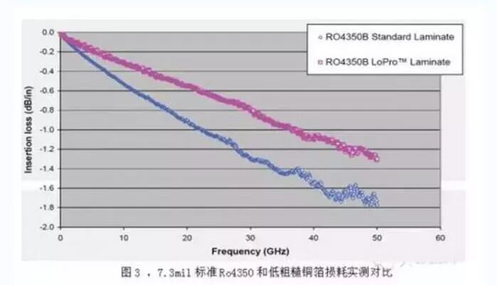
Low loss, stable Dk/Df parameters, low dispersion, small variation coefficients with frequency and environmental changes, small tolerances in material thickness and resin content (good impedance control), and if the traces are long, consider low roughness copper foil. Additionally, high-speed circuit designs require simulation in the early stages, and simulation results serve as reference standards for design. “Xingsen Technology – Agilent (High-Speed/RF) Joint Laboratory” has solved the problem of inconsistencies between simulation results and testing, conducting extensive simulations and actual testing for closed-loop verification, achieving consistency between simulation and measurement through unique methods.
03
Timely Availability of Materials
Many high-frequency materials have very long procurement cycles, even 2-3 months; except for the commonly used high-frequency material RO4350, which has stock, many high-frequency boards require customers to provide materials. Therefore, it is essential to communicate with manufacturers in advance and prepare materials as early as possible.
04
Cost Factors
Consider the price sensitivity of the product, whether it is a consumer product or applications in communications, medical, industrial, or military fields.
05
Applicability of Laws and Regulations
Must comply with environmental regulations of different countries, meeting RoHS and halogen-free requirements.
Among all these factors, the operating speed of high-speed digital circuits is the primary consideration for PCB selection. The higher the circuit speed, the smaller the selected PCB’s DF value should be. Circuit board materials with medium and low loss will be suitable for 10Gb/s digital circuits; materials with lower loss will be suitable for 25Gb/s digital circuits; and ultra-low loss materials will be suitable for even faster high-speed digital circuits, with speeds of 50Gb/s or higher.
From the perspective of material DF:
DF between 0.01 and 0.005 is suitable for circuit boards with an upper limit of 10Gb/s digital circuits;
DF between 0.005 and 0.003 is suitable for circuit boards with an upper limit of 25Gb/s digital circuits;
DF not exceeding 0.0015 is suitable for 50Gb/s or even faster digital circuits.
This article summarizes how to select high-speed board materials and design considerations. In practice, applications should be analyzed based on specific cases.

Screenshots of Some Electronic Books
【Complete Set of Hardware Learning Materials Collection】