 Search WeChat
 Technical Training1. Action Description
1. Achieve forward and reverse rotation of the inverter, read and write frequency;
2. Hardware Devices
1. Weilun Touch Screen: MT6071IP
2. Mitsubishi Inverter E700 Series
3. Software
Weilun Touch Screen Software:

4. Software Operation StepsStep 1:
Double-click to open the touch screen software icon to start the software.
Step 2:
Create a new project as shown in Figure 1, select the model MT6000/8000 series
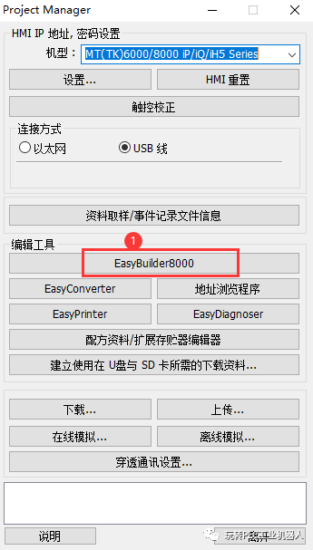
Figure 1
Step 3:
Click on the location in Figure 1 to create a new project as shown in Figure 2
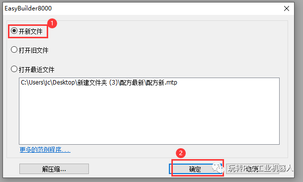
Figure 2
Step 4:
Select the specific model as shown in Figure 3.
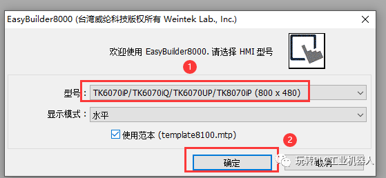
Figure 3
Step 5:
As shown in Figure 4, click the add button 1, select MODBUS RTU driver
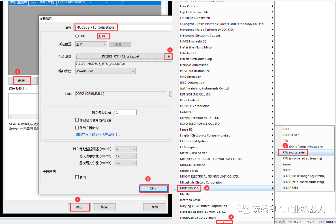
Figure 4
Step 6:
As shown in Figure 5, pay attention to the communication parameters; the settings of the inverter and the touch screen must be consistent, otherwise communication will fail.
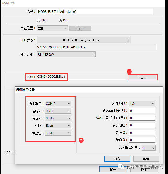
Figure 5
Step 7:
As shown in Figure 6, edit the screen.
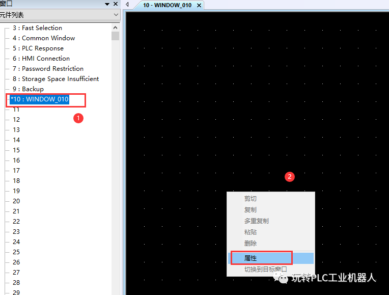
Figure 6
Step 8:
As shown in Figure 7, select the background color
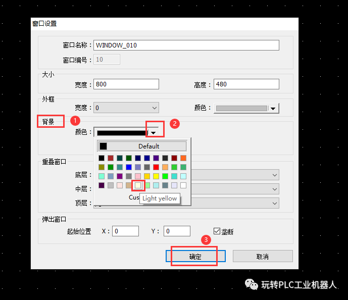
Figure 7
Step 9:
As shown in Figure 8, add a title
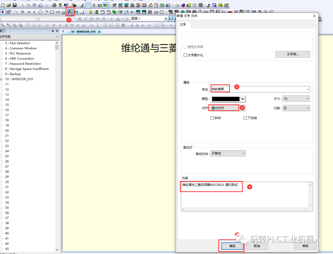
Figure 8
Step 10:
As shown in Figure 9, add a multi-state switch; the MODBUS address of the Mitsubishi inverter needs to be reduced by 40001; if the control start-stop address is 40009, the actual address is 8. The same calculation method applies to other MODBUS addresses. Forward, reverse, stop are all multi-state switches, just set the constant, as shown in Figure 10, refer to the inverter manual for specific instructions.
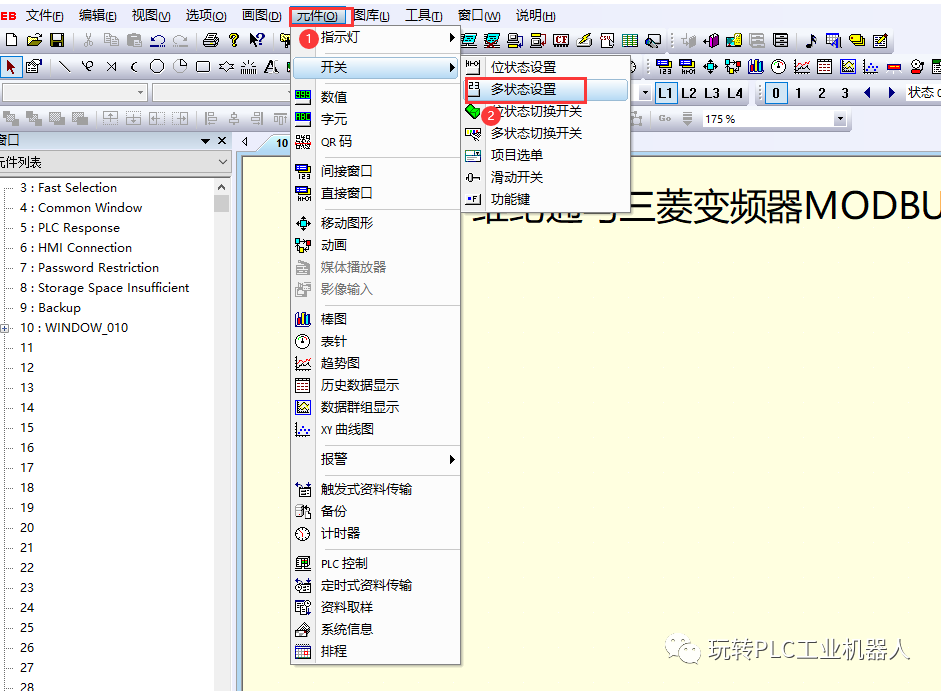
Figure 9
Step 11:
As shown in Figure 10, click 1, then fill in the corresponding function, preferably according to the inverter manual.
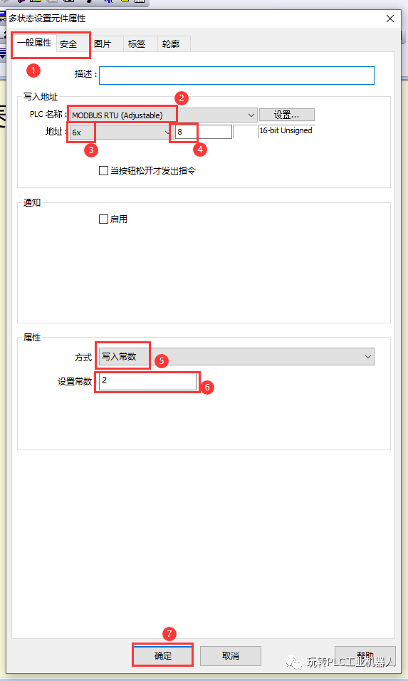
Figure 10
Step 12:
As shown in Figure 11, you can change the display properties of the control button.
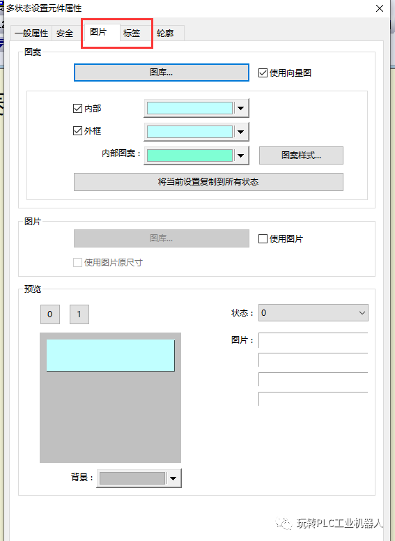
Figure 11
Step 13:
As shown in Figure 12, create a numeric component and write parameters to the button
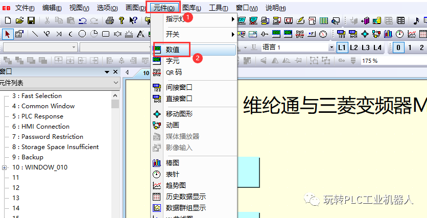
Figure 12
Step 14:
As shown in Figure 13, fill in the specific parameters,
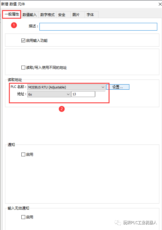
Figure 13
Step 15:
As shown in Figure 14, set the numeric format
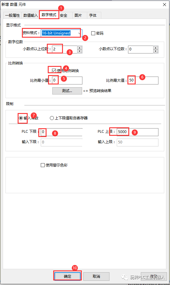
Figure 14
Step 16:
As shown in Figure 15, create an output frequency numeric component
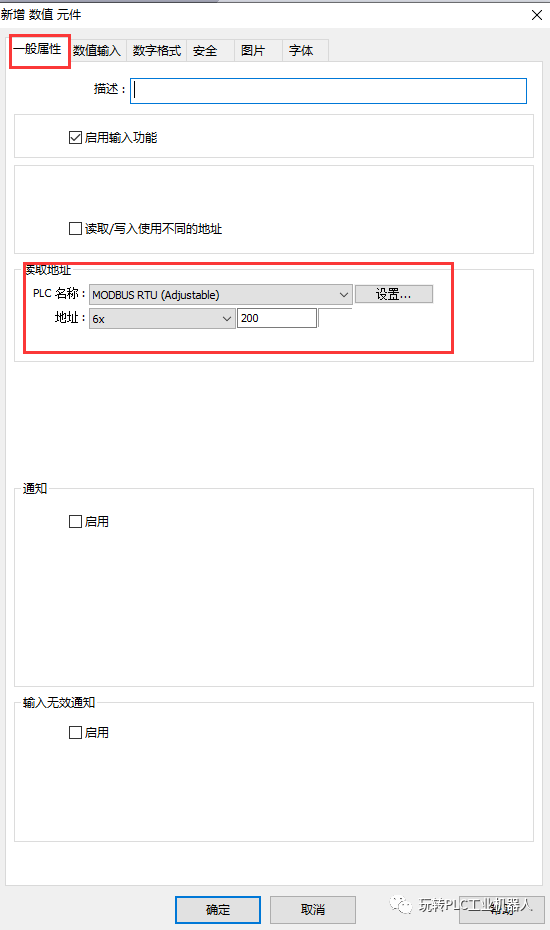
Figure 15
Step 17:
As shown in Figure 16, set the data format,
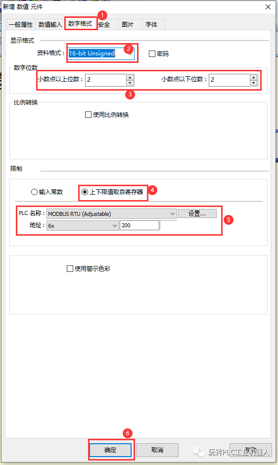
Figure 16
Step 18:
As shown in Figure 17, create an output current numeric component
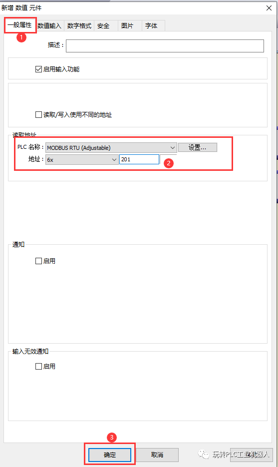
Figure 17
Step 19:
As shown in Figure 18, set the numeric format
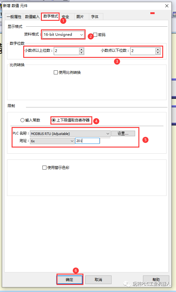
Figure 18
Step 20:
As shown in Figure 19, create an output voltage numeric component
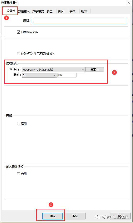
Figure 19
Step 21:
As shown in Figure 20, set the numeric format
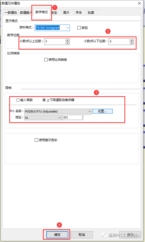
Figure 20
Step 22:
The interface is shown in Figure 21, save and download to the touch screen
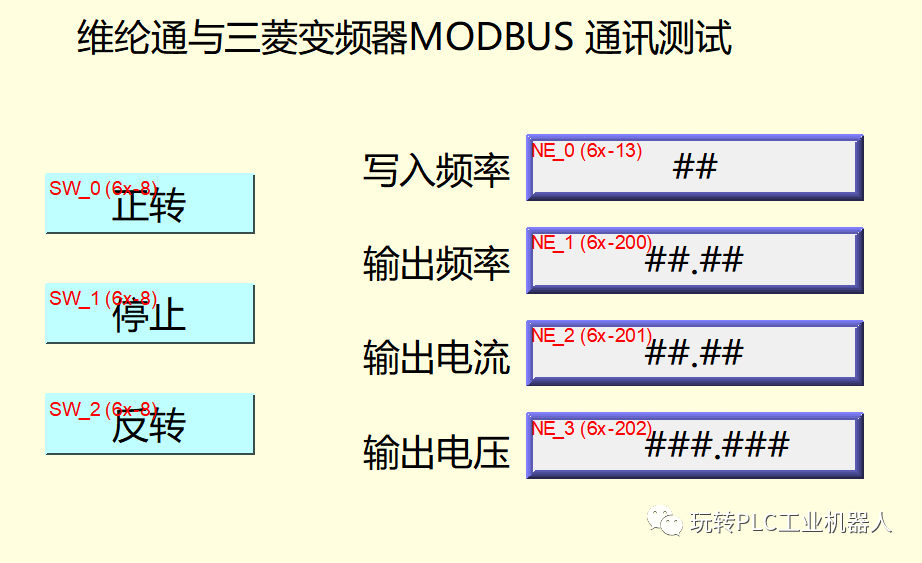
Figure 21
5. Inverter Parameter Settings and Wiring, MODBUS Address Conversion
1. Parameter Settings As shown in Figure 22, after setting the parameters of the inverter, it needs to be restarted.
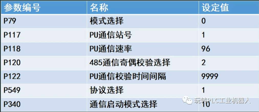
Figure 22
2. MODBUS Address Conversion as shown in Figure 23
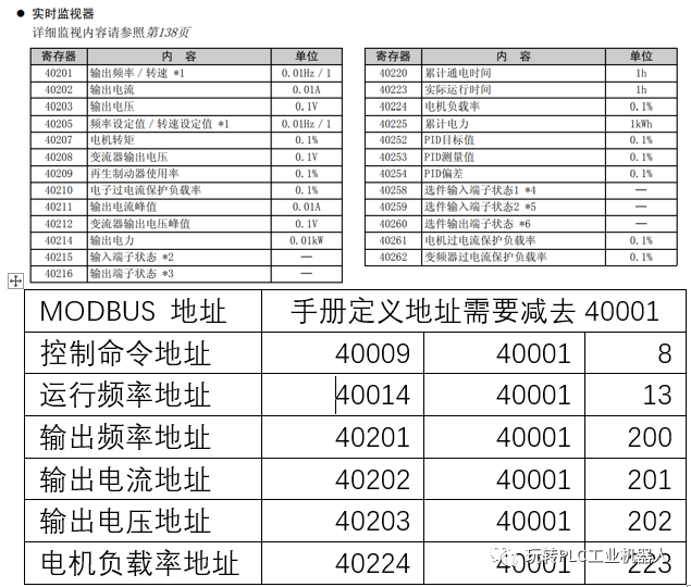
Figure 23
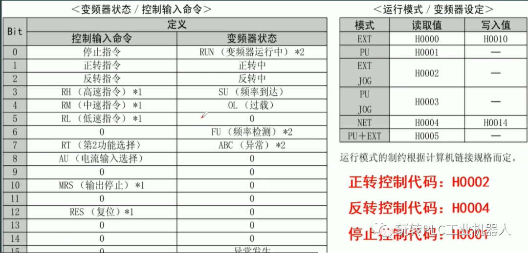
Figure 24 defines the control input command
Bit0=1 Bit1=1 Bit2=1
When Bit0 is 1, the stop command.
When Bit1 is 1, binary 0010, converted to decimal 2, forward command.
When Bit2 is 1, binary 0100, converted to decimal 4, reverse command.
3. Wiring
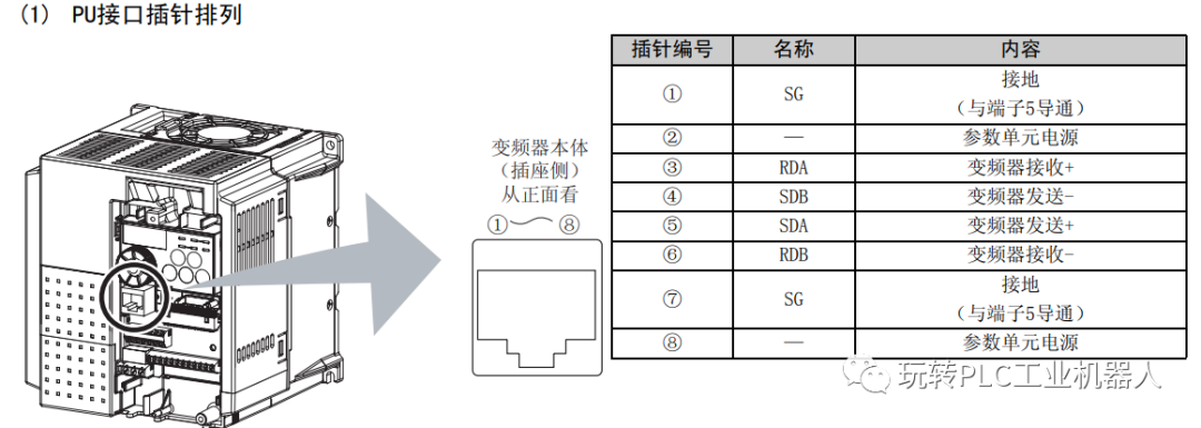
Figure 25 Inverter wiring diagram
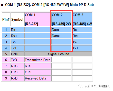
Figure 26 Touch screen wiring diagram
The 35 of the inverter is shorted to the DATA+ of the touch screen COM2 port. 46 is shorted to the DATA- of the touch screen COM2 port. If communication fails, swap the DATA+ and DATA- wiring.
Summary
1. Pay attention to parameter settings and MODBUS address conversion.
2. Wiring must be correct.
3. The parameter settings of the inverter and the touch screen must be consistent.
Source: Technical Training Network Original, Author: He Dongge; Reproduction without authorization is prohibited, and violators will be prosecuted!
HISTORY/Previous Recommendations
2021 Electrical Worker Junior Exam Question Bank Complete (with answers)
3 Must-Have Tools for Electricians, Just One Click to Use with WeChat!
【Collect】 The “Path” of a Ten-Year Veteran Electrician, Secrets to Earning Over Ten Thousand a Month!
Five Major Electrical Drawing Software (CAD, Eplan, CADe_simu…), Which One Do You Pick?
Latest Electrical Version CAD Drawing Software, with Detailed Installation Tutorial!
Latest Electrical Drawing Software EPLAN, with Detailed Installation Tutorial!
Common Issues for Beginners Using S7-200 SMART Programming Software (with download links)
Super Complete Electrical Calculation EXCEL Sheets, Automatically Generated! No Need to Ask for Electrical Calculations!
Bluetooth Headphones, Beginner Books for Electricians/PLC, Get Your Electrical Gifts!
Basic Skills of PLC Programming: Ladder Diagrams and Control Circuits (with 1164 Practical Cases of Mitsubishi PLC)
Still Can’t Understand Electrical Diagrams? Electrician Drawing Basics, Simulation Software Available, Quickly Get Started with Theory and Practice!
12 Free Electrician Video Courses, 10GB Software/E-books, 30 Days of Free Electrician Live Courses!
Don’t forget to like + check it out!
 Click “Read Original” to Learn PLC/Electrician Courses for Free