Hello, I am Little Fish who loves fish-flavored dishes in ROS. In the last section, we completed the measurement of distance at a specified angle. This section will synthesize it into a ROS LaserScan message and publish it to the upper computer through Micro-ROS, ultimately achieving visualization in RViz2.
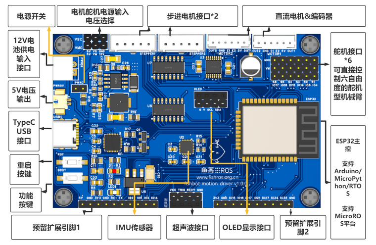
Hardware Development Platform
For convenience in learning, the hardware that accompanies this tutorial is the Micro-ROS learning board made by Little Fish. This board can also serve as the main control board for building a physical mobile robot in the next chapter and later as the driver board for making a robotic arm.
The onboard resource diagram is as follows:
This main control board can be purchased directly from Little Fish’s shop, offering great value. Click the bottom left corner to read the original text and go directly to the fish-flavored shop.
1. Introduction to Radar Messages
Using the command ros2 interface show sensor_msgs/msg/LaserScan, you can see the definition of the radar data interface in ROS2.
# Single scan from a planar laser range-finder## If you have another ranging device with different behavior (e.g. a sonar# array), please find or create a different message, since applications# will make fairly laser-specific assumptions about this data
std_msgs/Header header # timestamp in the header is the acquisition time of    builtin_interfaces/Time stamp        int32 sec        uint32 nanosec    string frame_id                             # the first ray in the scan.                             #                             # in frame frame_id, angles are measured around                             # the positive Z axis (counterclockwise, if Z is up)                             # with zero angle being forward along the x axis
float32 angle_min            # start angle of the scan [rad]float32 angle_max            # end angle of the scan [rad]float32 angle_increment      # angular distance between measurements [rad]
float32 time_increment       # time between measurements [seconds] - if your scanner                             # is moving, this will be used in interpolating position                             # of 3d pointsfloat32 scan_time            # time between scans [seconds]
float32 range_min            # minimum range value [m]float32 range_max            # maximum range value [m]
float32[] ranges             # range data [m]                             # (Note: values < range_min or > range_max should be discarded)float32[] intensities        # intensity data [device-specific units].  If your                             # device does not provide intensities, please leave                             # the array empty.
1.1 Header Section
The header section mainly sets the radar’s frame_id and timestamp. In Micro-ROS, it can be assigned like this:
pub_msg.header.frame_id = micro_ros_string_utilities_set(pub_msg.header.frame_id, "laser"); // Initialize message content
int64_t current_time = rmw_uros_epoch_millis();
pub_msg.header.stamp.sec = current_time * 1e-3;
pub_msg.header.stamp.nanosec = current_time - pub_msg.header.stamp.sec * 1000;
1.2 Data Section
•angle_min The minimum measurement angle in the current data•angle_max The maximum measurement angle in the current data•angle_increment We default to 1 degree per measurement, so we can write it directly
<span> pub_msg.angle_increment = <span>1.0</span> / <span>180</span> * PI;</span>•time_increment The time increment between each data point, which can be directly calculated by dividing the total scan time by the number of points•scan_time The time from the start of scanning to the end of scanning•range_min The minimum range can be set directly; we set it to 0.05, which is 5 cm•range_max The maximum range, which we set to 5.0 m•ranges The array of measured distance values•intensities The measured intensity, which we can ignore here
2. Code Writing
Modify directly on the previous project, and the complete code is as follows. We publish 10 points at a time and start the dual-core of the ESP32 while synchronizing time to ensure the timestamp of the radar data is correct.
#include <Arduino.h>#include <micro_ros_platformio.h>#include <WiFi.h>#include <rcl/rcl.h>#include <rclc/rclc.h>#include <rclc/executor.h>#include <ESP32Servo.h>
#include <sensor_msgs/msg/laser_scan.h>#include <micro_ros_utilities/string_utilities.h>
#define PCOUNT 10#define Trig 27 // Define the Arduino pin connected to SR04#define Echo 21
rclc_executor_t executor;rclc_support_t support;rcl_allocator_t allocator;rcl_node_t node;
rcl_publisher_t publisher;           // Declare topic publisher
sensor_msgs__msg__LaserScan pub_msg; // Declare message file
Servo servo1;bool connected_agent = false;
void microros_task(void *param){
  IPAddress agent_ip;                                                    // Set up Micro-ROS communication via WIFI  agent_ip.fromString("192.168.2.105");                                  // Get IP address from string  set_microros_wifi_transports("fishbot", "12345678", agent_ip, 8888);   // Set wifi name, password, computer IP, port number  delay(2000);                                                           // Delay for a while to wait for settings to complete  allocator = rcl_get_default_allocator();                               // Initialize memory allocator  rclc_support_init(&support, 0, NULL, &allocator);                      // Create initialization options  rclc_node_init_default(&node, "example20_simple_laser", "", &support); // Create node  rclc_publisher_init_default(                                           // Publish initialization      &publisher,      &node,      ROSIDL_GET_MSG_TYPE_SUPPORT(sensor_msgs, msg, LaserScan),      "/scan");
  rclc_executor_init(&executor, &support.context, 1, &allocator);                             // Create executor  pub_msg.header.frame_id = micro_ros_string_utilities_set(pub_msg.header.frame_id, "laser"); // Initialize message content  pub_msg.angle_increment = 1.0 / 180 * PI;  pub_msg.range_min = 0.05;  pub_msg.range_max = 5.0;
  while (true)  {    delay(10);    if (!rmw_uros_epoch_synchronized()) // Check if time is synchronized    {      rmw_uros_sync_session(1000); //  Synchronize time      continue;    }    connected_agent = true;    rclc_executor_spin_some(&executor, RCL_MS_TO_NS(100)); // Loop to process data  }}
float get_distance(int angle){  static double mtime;  servo1.write(angle);     // Move to specified angle  delay(25);               // Stabilize position  digitalWrite(Trig, LOW); // Measure distance  delayMicroseconds(2);  digitalWrite(Trig, HIGH);  delayMicroseconds(10); //  Generate a 10us high pulse to trigger SR04  digitalWrite(Trig, LOW);  mtime = pulseIn(Echo, HIGH);                  // Detect pulse width, note that the return value is in microseconds (us)  float detect_distance = mtime / 58.0 / 100.0; //  Calculate distance; the output distance unit is centimeters (cm)  Serial.printf("point(%d,%f)\n", angle, detect_distance);  return detect_distance;}
void setup(){  Serial.begin(115200);  pinMode(Trig, OUTPUT);     // Initialize servo and ultrasonic  pinMode(Echo, INPUT);      // To detect the pulse width input on the pin, it must be set to input state first  servo1.setPeriodHertz(50); // Standard 50hz servo  servo1.attach(4, 500, 2500);  servo1.write(90.0);  xTaskCreatePinnedToCore(microros_task, "microros_task", 10240, NULL, 1, NULL, 0);}
void loop(){  if (!connected_agent)    return;
  static float ranges[PCOUNT + 1];  for (int i = 0; i < int(180 / PCOUNT); i++)  {    int64_t start_scan_time = rmw_uros_epoch_millis();    for (int j = 0; j < PCOUNT; j++)    {      int angle = i * 10 + j;      ranges[j] = get_distance(angle);    }    pub_msg.angle_min = float(i * 10) / 180 * PI;       // End angle    pub_msg.angle_max = float(i * (10 + 1)) / 180 * PI; // End angle
    int64_t current_time = rmw_uros_epoch_millis();    pub_msg.scan_time = float(current_time - start_scan_time) * 1e-3;    pub_msg.time_increment = pub_msg.scan_time / PCOUNT;    pub_msg.header.stamp.sec = current_time * 1e-3;    pub_msg.header.stamp.nanosec = current_time - pub_msg.header.stamp.sec * 1000;    pub_msg.ranges.data = ranges;    pub_msg.ranges.capacity = PCOUNT;    pub_msg.ranges.size = PCOUNT;    rcl_publish(&publisher, &pub_msg, NULL);    delay(10);  }}
3. Download and Test
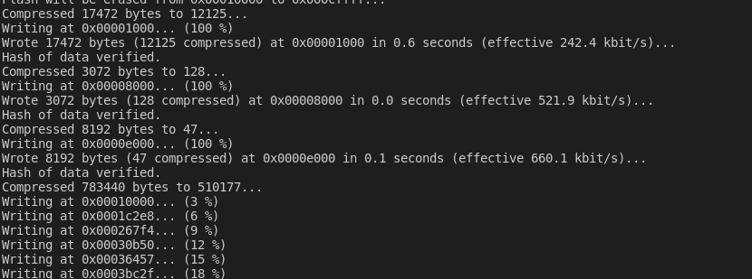
Download the code
Start the agent.
docker run -it --rm -v /dev:/dev -v /dev/shm:/dev/shm --privileged --net=host microros/micro-ros-agent:$ROS_DISTRO udp4 --port 8888 -v6
Test
ros2 node list
ros2 topic list
ros2 topic echo /scan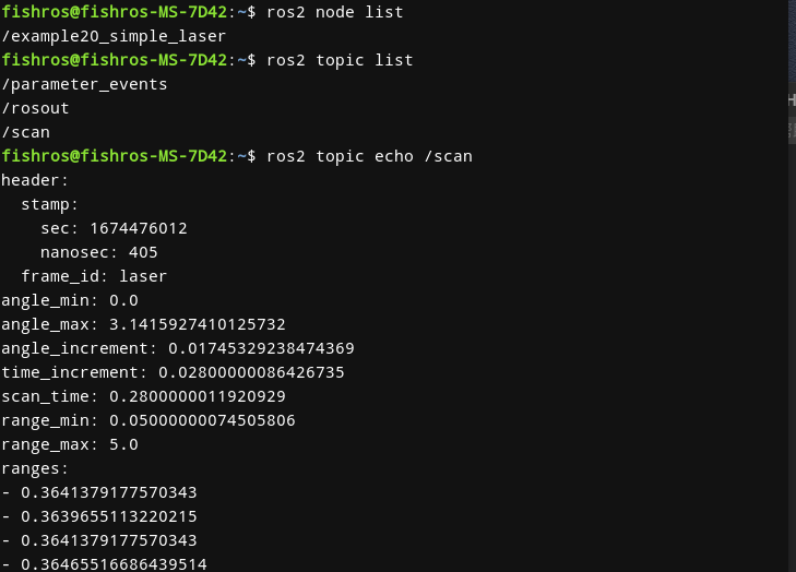
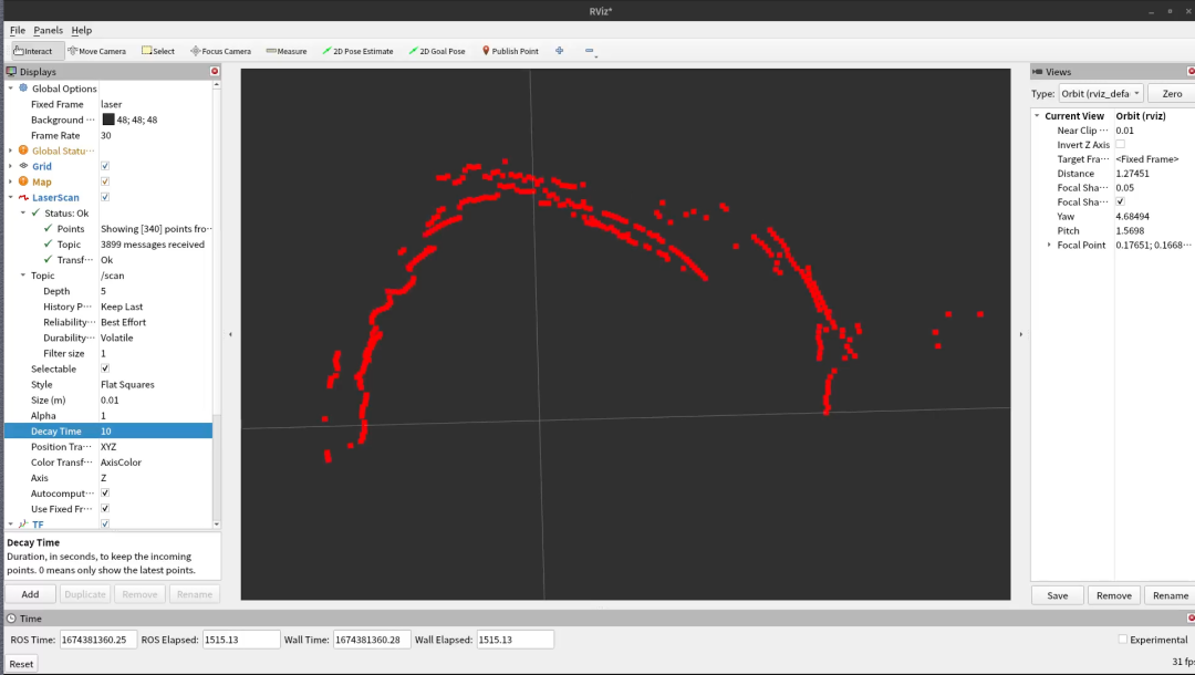
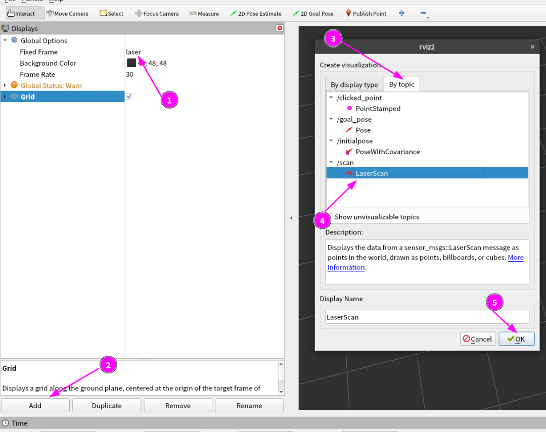
Then open the terminal and enter rviz2 to open RViz.
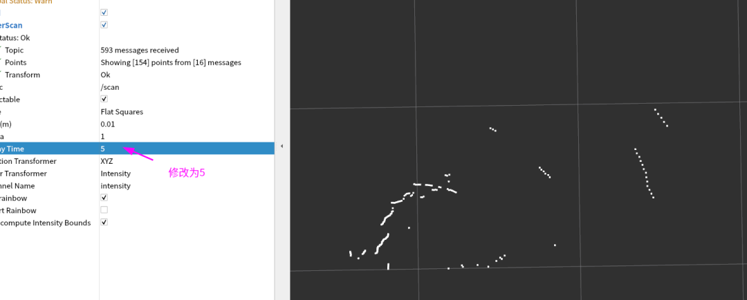
Modify the configuration to display data from the past 5 seconds.
4. Summary
In this section, we successfully simulated radar data using ultrasonic and servos, synthesizing it into a scan published to the computer for visualization using RViz2. Thus, we have completed all courses on ROS2 hardware control. Next, you will embark on the courses for mobile robots and robotic arms. Please be prepared and continue onward.