Virtualization technology improves resource utilization and flexibility by allowing multiple virtual machines (VMs) to share underlying physical resources, but it also brings challenges in security and isolation. Hard isolation is a key mechanism to ensure that VMs do not interfere with each other, preventing malicious attacks or accidental failures from spreading from one VM to others.
The trend of “one chip, multiple screens” architecture in intelligent cockpits requires a single SoC chip to drive multiple functional domains such as instrument clusters, central control, entertainment, and HUD simultaneously. The functional isolation scheme under the “one domain, one chip” architecture clearly cannot meet the physical isolation requirements for safety-critical systems like instrument clusters and non-safety systems like entertainment within a single chip. Ensuring that high-priority tasks are not preempted by low-priority processes becomes a necessary issue to address.
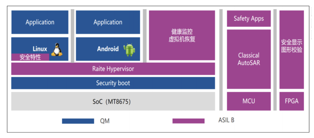
Layered architecture of Hypervisor in intelligent cockpits, source: Qiang Ge’s Breadcrumbs
The integration of virtualization and hard isolation technologies effectively addresses this issue. By implementing logical isolation through the Hypervisor virtualization layer, combined with hardware-level physical resource partitioning, intelligent cockpits can construct a “shared yet independent” mixed operating environment on a single chip.
1. Logical Isolation Architecture of Hypervisor
1. Core Functions and Layered Logic of Hypervisor
The Hypervisor, known as a virtual machine monitor, is a lightweight software layer located between the hardware and the operating system, whose core function is to create and manage multiple VMs, each capable of running different operating systems and applications independently.
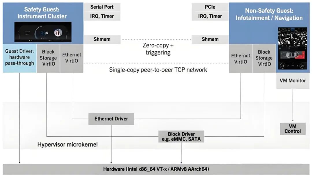
In intelligent cockpits, a typical layered architecture includes the hardware layer, the Hypervisor layer, and the VM layer. The hardware layer consists of physical resources such as SoC chips, memory, and peripheral controllers; the Hypervisor layer is responsible for resource allocation, VM scheduling, and hardware access control; the VM layer includes independent functional domains such as the instrument system running Linux RTOS, the entertainment system running Android Automotive, and the HUD control module.
2. Resource Allocation and Priority Management
The Hypervisor achieves resource isolation and dynamic scheduling through the following mechanisms:
CPU virtualization. It employs time-slice rotation (Round-Robin) or fixed priority scheduling algorithms. For example, the instrument system is assigned as a real-time task (priority 0), while the entertainment system is a normal task (priority 5), ensuring that the instrument process always has priority access to CPU resources;
Memory virtualization. It allocates independent memory regions for each VM through address space mapping, preventing out-of-bounds access. For instance, the QNX Hypervisor supports dynamic hot-plugging of memory regions, allowing runtime adjustments of memory quotas for each VM;
I/O virtualization. It uses passthrough or virtual device emulation techniques. Critical peripherals (such as CAN bus controllers) are typically passed through to the instrument system, while shared resources like GPUs are allocated by the Hypervisor.
3. Dual Assurance of Real-time Performance and Security
First, support for real-time operating systems (RTOS). The instrument system must meet ASIL-B functional safety requirements, thus it often runs on real-time OS like QNX or VxWorks. The Hypervisor ensures that the response latency of instrument tasks is below 10ms through interrupt virtualization and low-latency response mechanisms, such as ARM’s GICv4 interrupt controller;
Second, secure boot and encrypted isolation. From the Bootloader stage, the Hypervisor performs digital signature verification for each VM and establishes encrypted communication channels using TrustZone technology to prevent malicious code from spreading across VMs.
2. Hardware Hard Isolation and Deterministic Partitioning of Physical Resources
1. Technical Implementation Path of Hard Isolation
Hardware hard isolation is achieved through chip-level design, partitioning physical resources such as CPU cores, memory controllers, and peripheral interfaces by functional domains, forming a “physical fence” that cannot be breached by software. For example, in NXP’s S32G series chips:
CPU core binding. Four Cortex-A53 cores are divided into two groups, with cores 0-1 dedicated to the instrument system and cores 2-3 to the entertainment system, disabling cache coherence protocols between the two groups;
Memory physical partitioning. The memory protection unit (MPU) divides the DDR into multiple independent regions, for instance, the instrument system exclusively uses the range 0x80000000-0x8FFFFFFF, while the entertainment system uses 0x90000000-0x9FFFFFFF, ensuring hardware-level isolation to eliminate memory out-of-bounds risks;
Peripheral access control. Critical peripherals such as CAN FD and Ethernet TSN are directly connected to specific CPU cores through hardware firewalls. For example, the CAN controller only responds to interrupt requests from core 0, preventing direct access from the entertainment system.
2. Implementation of Automotive Safety Standards
ASIL-D level fault tolerance. The hardware isolation module must meet the highest safety level requirements of ISO 26262. When a deadlock fault is detected in the CPU core of the instrument system, the hardware watchdog (Watchdog Timer) can trigger a reset within 50ms, and the entertainment system core remains unaffected;
Temperature and power consumption monitoring. Each physical partition is equipped with independent sensors. For example, when the temperature of the instrument system core exceeds 105°C, hardware-level thermal shutdown only turns off that partition, avoiding total chip failure.
3. Engineering Practice of Hybrid Isolation Strategies
In practical projects, virtualization and hard isolation are often used in combination to balance flexibility and security. For safety-critical domains such as instrument clusters and ADAS HMI, a hard isolation + RTOS solution is generally adopted to ensure functional determinism; while non-safety domains like entertainment and navigation use virtualization + general OS solutions to enhance resource utilization.
For example, the cockpit controller of NIO ET7 uses NXP S32G2 chips, with the instrument system running on hard-isolated cores 0-1 and the entertainment system running on cores 2-3 managed by the Hypervisor, sharing the GPU but restricting access through a hardware firewall.
3. Technical Relevance and Collaborative Interaction
1. Interaction with Multi-Screen Linked Architecture. This includes display channel isolation and cross-VM rendering. Display channel isolation is achieved through hard-isolated MIPI controllers driving different screens.
For instance, the instrument screen uses MIPI-DSI channel 0, the central control screen uses channel 1, and the Hypervisor ensures independent bandwidth allocation for each channel; cross-VM rendering requires that the 3D instrument panel and entertainment system interface share GPU resources. AMD’s Vulkan SC driver supports secure context switching in hard-isolated environments, preventing graphic data leakage.
2. Collaboration with In-Vehicle Communication Networks. This includes TSN network isolation and inter-VM communication. TSN network isolation processes clock synchronization messages by hard-isolated cores, ensuring transmission jitter is below 1μs; while inter-VM communication uses shared memory + semaphore mechanisms. For example, the navigation system (running on the entertainment VM) writes path data into a shared memory area, and the instrument VM notifies reading the data through interrupts, without the involvement of the network protocol stack.
3. Fusion Challenges with Autonomous Driving Domains. When the cockpit and intelligent driving domains share the same chip (such as NVIDIA Thor), further isolation must be reinforced, such as designing functional safety islands to reserve dedicated computing units for intelligent driving functions, physically isolating them from the cockpit domain; and in hybrid critical scheduling, the Hypervisor must support mixed deployment of AUTOSAR Adaptive and Linux to meet different real-time requirements.
4. Application Cases
The AITO M5/Zhijie S7/Avita 12 equipped with Huawei’s HarmonyOS intelligent cockpit uses Huawei’s self-developed Kirin 990A automotive-grade SoC, implementing dual-system isolation through a QNX-modified Hypervisor virtualization layer; the system is divided into an instrument domain running Huawei’s self-developed microkernel RTOS (ASIL-B level) and an entertainment domain running the HarmonyOS vehicle version, with physical resource partitioning achieved through hard-isolated memory partitions (MPU) and interrupt controller binding.
In terms of interactive collaboration, it supports AR-HUD and central control screen 3D navigation data synchronization, achieving shared memory and semaphore mechanisms with a response latency of less than 20ms.
The design of the ideal L9’s multimodal interaction and cockpit-driving fusion. Dual Orin-X chips handle intelligent driving and cockpit tasks respectively, dynamically allocating computing power through PCIe Switch.
In driving mode, 80% of computing power is allocated to NOA navigation, and 20% is used for AR-HUD rendering; in entertainment mode, 70% of computing power shifts to 5K co-driver screen game rendering, ensuring 30% for basic driving functions; the safety isolation strategy employs Infineon’s TC397 + QNX Hypervisor, with the instrument domain fault rate below 1 FIT (10^9 hours).
In terms of user experience, TOF sensors recognize 15 standard gestures, such as fist gestures to adjust volume, with an error rate of less than 0.1%; the navigation system and ADAS share high-precision map data, and the HUD can overlay lane-level risk alerts, such as construction area warnings.
END