JDY-31
The JDY-31 Bluetooth module is a small device like the one shown below. It can be purchased for about seven to eight yuan on Taobao; do not buy it for more than ten yuan.
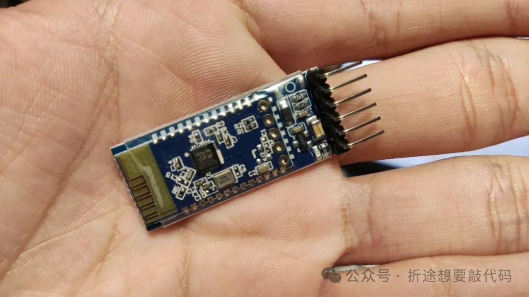
The JDY has a total of 6 pins, but to make it work, we only need to connect two wires: VCC and GND. Connect VCC to a voltage between 3.6V and 6V (5V is recommended), and connect GND to ground. Once this is done, the JDY31 will start working, and our phone will be able to find the JDY Bluetooth.
After pairing, our phone can communicate with the JDY31. However, communicating only with JDY31 is not very meaningful, so we will connect JDY31 to a microcontroller, allowing us to control the microcontroller via Bluetooth from our phone.
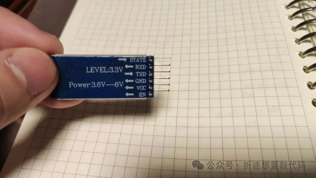
We connect the RXD of JDY31 to the TXD of our STM32F103, and the TXD of JDY31 to the RXD of our STM32F103 (it is recommended to use the resources of USART1, specifically GPIOA pins 9 and 10, because JDY’s operating voltage is higher, and the general pins of STM32F103 cannot handle it, while the pins of USART1 can accept 5V voltage; refer to the pin definition table for specifics).
Thus, as long as our phone connects to JDY31 via Bluetooth, and JDY31 is connected to STM32F103 via serial port, any data sent from the phone via Bluetooth assistant will be received directly by JDY and forwarded to STM32F103. Likewise, any data sent from STM32F103 via serial will be transmitted back to our phone through JDY31.
So Bluetooth communication isn’t that difficult; in fact, modules like JDY31 make Bluetooth communication easier.
The remaining two pins are STATE and EN. In short, EN is not used, while the STATE pin will output a high level when connected to JDY Bluetooth, which can be used to connect an LED for a visual indication of Bluetooth connection status. However, it is not necessary, as JDY has a small red indicator light that blinks when waiting for a connection and stays solid when connected.
Using AT Commands to Control JDY31
The above discussed how to perform Bluetooth communication using JDY31.
If we want to modify some configuration information of JDY (such as Bluetooth name, connection password, etc.), we need to use AT commands to control JDY.
AT commands sound cool, but they are essentially just a series of specific strings.
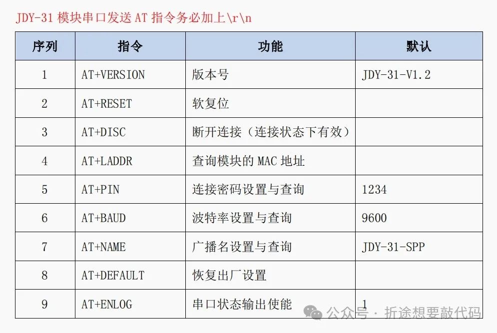
For example, to query the version number, I simply let STM32F103 send the string “AT+VERSION\r\n” via the serial port, which means the command followed by “\r\n”. JDY31 will then send the version number back through the serial port. Essentially, it is still serial communication.
Overall, there are only nine commands, and there’s not much to say about them. Below, I will briefly mention commands with parameters.
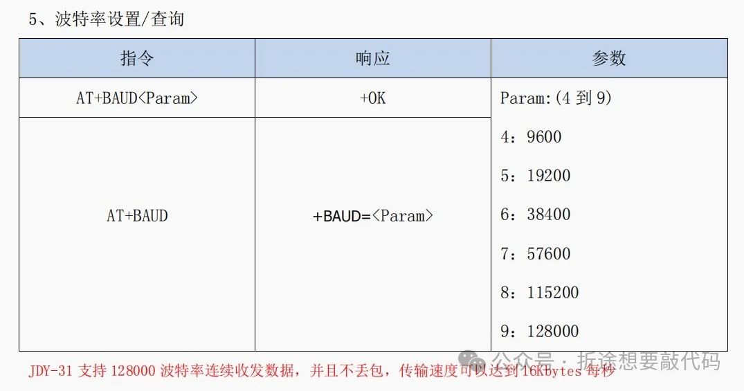
The baud rate command can have parameters added to modify the baud rate, but it is not freely set. For example, to set a baud rate of 9600, the command sent should be “AT+BAUD<4>\r\n”. Other baud rate parameters can be referenced from the image above.
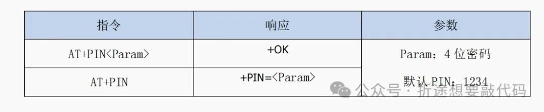
To set the pairing password, which defaults to 1234, simply send the desired new password as a parameter.
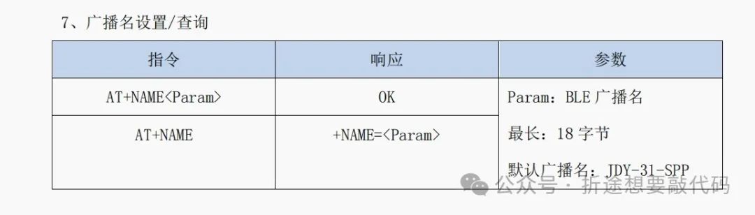
Setting the Bluetooth name will have a slight delay; you need to wait for the Bluetooth name to update when searched on the phone.
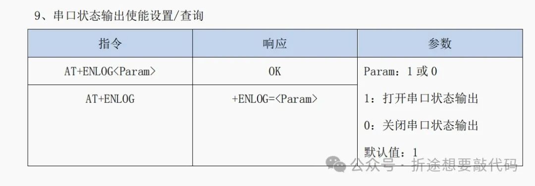
As mentioned, generally, once JDY31 connects to Bluetooth, the STATE pin will output a high level. If we disable this serial status output, the STATE pin will be as useless as the EN pin.
Using STM32F103 to Send AT Commands to JDY-31 via Serial
The following explanation should be paired with the code below.
There’s not much to say about opening the serial port; you can directly copy the code from my previous article on USART.
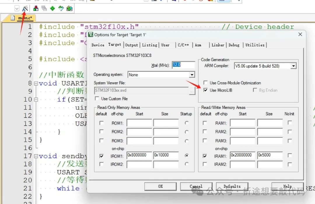
For ease of serial output, I’ve included the stdio library and redefined fputc, which allows us to use printf for serial output. Keil5 also requires configuration as shown below.
Next, we simply need to send AT commands. Note that there should be a delay between consecutive commands; otherwise, JDY31 might not respond (this is my guess, but JDY will ignore some commands).
The results are shown in the image below the code.
#include "stm32f10x.h" // Device header#include "Delay.h"#include <stdio.h> // Interrupt functionvoid USART1_IRQHandler(void){ // Check data receive flag if(SET==USART_GetFlagStatus(USART1,USART_FLAG_RXNE)){ uint16_t data=USART_ReceiveData(USART1); // Read the received data printf("%c",data); USART_ClearITPendingBit(USART1,USART_FLAG_RXNE); // Clear data receive flag }} void sendbyte(uint16_t Data){ // Send data USART_SendData(USART1,Data); // Wait for data to be sent while (USART_GetFlagStatus(USART1, USART_FLAG_TXE) == RESET);} // Redefine fputc to allow printf for serial outputint fputc(int ch, FILE *f){ sendbyte(ch); return ch;} int main(void){ RCC_APB2PeriphClockCmd(RCC_APB2Periph_USART1,ENABLE); RCC_APB2PeriphClockCmd(RCC_APB2Periph_GPIOA,ENABLE); GPIO_InitTypeDef itd; itd.GPIO_Mode=GPIO_Mode_AF_PP; // Multiplexed push-pull output itd.GPIO_Pin=GPIO_Pin_9; // TX pin itd.GPIO_Speed=GPIO_Speed_2MHz; // This can be arbitrary GPIO_Init(GPIOA,&itd); itd.GPIO_Mode=GPIO_Mode_IN_FLOATING;// Floating input itd.GPIO_Pin=GPIO_Pin_10; // RX pin GPIO_Init(GPIOA,&itd); USART_InitTypeDef uitd; uitd.USART_BaudRate=9600; // Baud rate uitd.USART_HardwareFlowControl=USART_HardwareFlowControl_None; // Hardware flow control uitd.USART_Mode=USART_Mode_Rx|USART_Mode_Tx; // Serial mode uitd.USART_Parity=USART_Parity_No; // Parity uitd.USART_StopBits=USART_StopBits_1; // Stop bit length uitd.USART_WordLength=USART_WordLength_8b; // Word length for transmission USART_Init(USART1,&uitd); USART_ITConfig(USART1,USART_IT_RXNE,ENABLE); // Enable USART receive interrupt NVIC_PriorityGroupConfig(NVIC_PriorityGroup_2); // NVIC interrupt configuration NVIC_InitTypeDef nitd; nitd.NVIC_IRQChannel=USART1_IRQn; nitd.NVIC_IRQChannelCmd=ENABLE; nitd.NVIC_IRQChannelPreemptionPriority=2; nitd.NVIC_IRQChannelSubPriority=2; NVIC_Init(&nitd); USART_Cmd(USART1,ENABLE); // Power on USART printf("AT+NAME\r\n"); // Query Bluetooth name Delay_ms(100); printf("AT+LADDR\r\n"); // Query MAC address Delay_ms(100); printf("AT+BAUD\r\n"); // Query baud rate Delay_ms(100); printf("AT+PIN\r\n"); // Query Bluetooth connection password Delay_ms(100); printf("AT+ENLOG\r\n"); // Query status output enable state Delay_ms(100); printf("AT+VERSION\r\n"); // Query version Delay_ms(100); printf("AT+NAME<JDY>\r\n"); // Change Bluetooth name, but it reacts slowly, so wait a bit for it to update while(1){ }}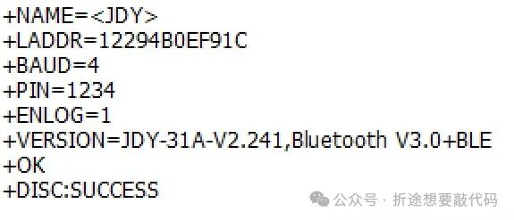
Ignore the last line; that was sent by JDY after the Bluetooth was disconnected.
JDY and Mobile Phone Bluetooth Communication
Bluetooth communication sounds cool, but in reality, once your phone connects to Bluetooth, the so-called Bluetooth communication is actually just using the serial port to send information. Therefore, we can directly use printf to output content, and the phone will receive it. However, we need to use a Bluetooth assistant to see the results; I used one provided by a Taobao seller, but you can find any one, even in WeChat mini-programs.
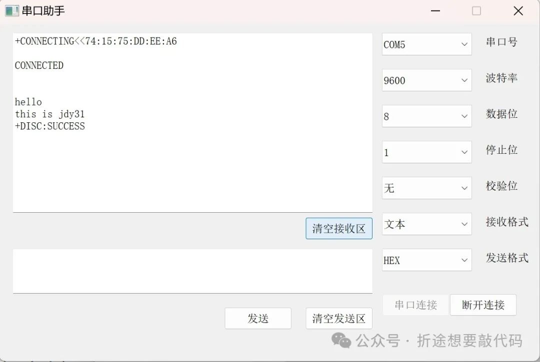
#include "stm32f10x.h" // Device header#include "Delay.h"#include <stdio.h> // Interrupt functionvoid USART1_IRQHandler(void){ // Check data receive flag if(SET==USART_GetFlagStatus(USART1,USART_FLAG_RXNE)){ uint16_t data=USART_ReceiveData(USART1); // Read the received data printf("%c",data); USART_ClearITPendingBit(USART1,USART_FLAG_RXNE); // Clear data receive flag }} void sendbyte(uint16_t Data){ // Send data USART_SendData(USART1,Data); // Wait for data to be sent while (USART_GetFlagStatus(USART1, USART_FLAG_TXE) == RESET);} int fputc(int ch, FILE *f){ sendbyte(ch); return ch;} int main(void){ RCC_APB2PeriphClockCmd(RCC_APB2Periph_USART1,ENABLE); RCC_APB2PeriphClockCmd(RCC_APB2Periph_GPIOA,ENABLE); GPIO_InitTypeDef itd; itd.GPIO_Mode=GPIO_Mode_AF_PP; // Multiplexed push-pull output itd.GPIO_Pin=GPIO_Pin_9; // TX pin itd.GPIO_Speed=GPIO_Speed_2MHz; // This can be arbitrary GPIO_Init(GPIOA,&itd); itd.GPIO_Mode=GPIO_Mode_IN_FLOATING;// Floating input itd.GPIO_Pin=GPIO_Pin_10; // RX pin GPIO_Init(GPIOA,&itd); USART_InitTypeDef uitd; uitd.USART_BaudRate=9600; // Baud rate uitd.USART_HardwareFlowControl=USART_HardwareFlowControl_None; // Hardware flow control uitd.USART_Mode=USART_Mode_Rx|USART_Mode_Tx; // Serial mode uitd.USART_Parity=USART_Parity_No; // Parity uitd.USART_StopBits=USART_StopBits_1; // Stop bit length uitd.USART_WordLength=USART_WordLength_8b; // Word length for transmission USART_Init(USART1,&uitd); USART_ITConfig(USART1,USART_IT_RXNE,ENABLE); // Enable USART receive interrupt NVIC_PriorityGroupConfig(NVIC_PriorityGroup_2); // NVIC interrupt configuration NVIC_InitTypeDef nitd; nitd.NVIC_IRQChannel=USART1_IRQn; nitd.NVIC_IRQChannelCmd=ENABLE; nitd.NVIC_IRQChannelPreemptionPriority=2; nitd.NVIC_IRQChannelSubPriority=2; NVIC_Init(&nitd); USART_Cmd(USART1,ENABLE); // Power on USART while(1){ printf("Hello World"); Delay_ms(2000); }}This is the complete information received by the serial assistant, including the connection and disconnection of Bluetooth.
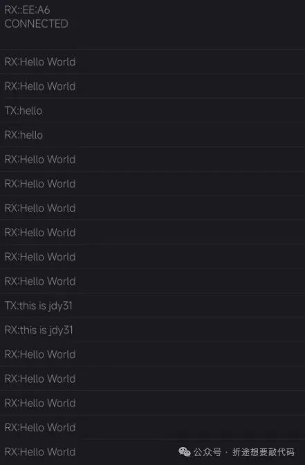
This is the information in the Bluetooth assistant on the phone; those starting with RX are received messages, and those starting with TX are sent from the phone.
Resource Acquisition
If anyone wants a special version of the serial assistant and the Android version of the Bluetooth assistant, you can follow my public account “Zhetu Wants to Code” and reply with the keyword “Bluetooth” to get it for free.