
UART Communication

When the receiving UART detects the start bit, it reads the bits in the data frame at a specific baud rate. The baud rate is a measure of the data transmission speed, expressed in bits per second (bps). Both UARTs must operate at approximately the same baud rate, and the baud rate between the transmitting and receiving UART can only differ by about 10%.
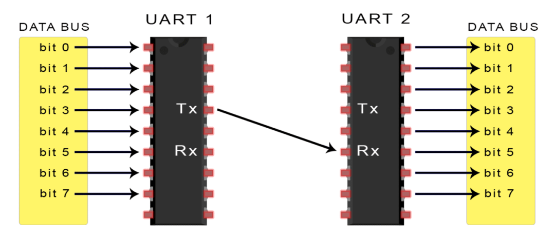
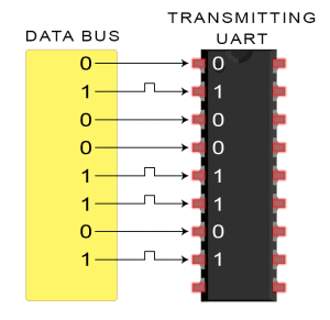
After the transmitting UART receives parallel data from the data bus, it adds a start bit, a parity bit, and a stop bit to form a data packet and serially outputs it bit by bit from the Tx pin, while the receiving UART reads the data packet bit by bit on its Rx pin.
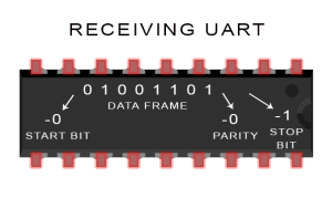
UART data includes 1 start bit, 5 to 9 data bits (depending on the UART), an optional parity bit, and 1 or 2 stop bits:
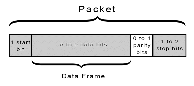
Start Bit
The UART data transmission line typically maintains a high voltage level when not transmitting data. When transmission begins, the transmitting UART pulls the transmission line from high to low within one clock cycle. When the receiving UART detects this transition from high voltage to low voltage, it starts reading the bits in the data frame at the baud rate.
Data Frame
The data frame contains the actual data being transmitted. If a parity bit is used, it can be 5 bits, up to a maximum of 8 bits. If no parity bit is used, the length of the data frame can be 9 bits.
Parity Bit
The parity bit is a way for the receiving UART to determine if any data changes occurred during transmission.After the receiving UART reads the data frame, it counts the number of bits that are 1 and checks whether the total is even or odd, and whether it matches the data.
Stop Bit
To signal the end of the data packet, the transmitting UART drives the data transmission line from low voltage to high voltage for at least two bit times.
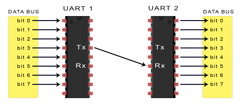
1. The transmitting UART receives parallel data from the data bus:
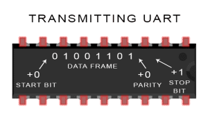
2. The transmitting UART adds the start bit, parity bit, and stop bit to the data frame:
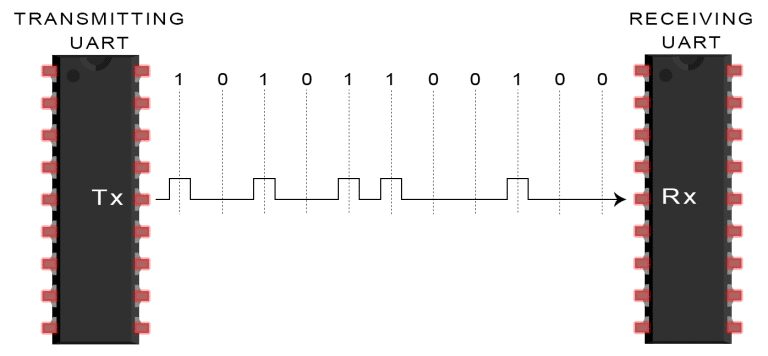
3. The entire data packet is serially sent from the transmitting UART to the receiving UART. The receiving UART samples the data line at the pre-configured baud rate:
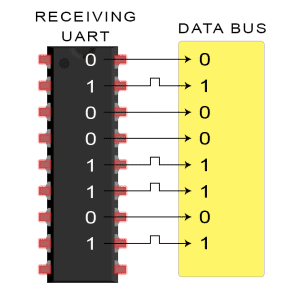
4. The receiving UART discards the start bit, parity bit, and stop bit from the data frame:
5. The receiving UART converts the serial data back into parallel data and transmits it to the data bus of the receiving end:
Advantages
-
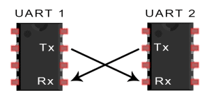
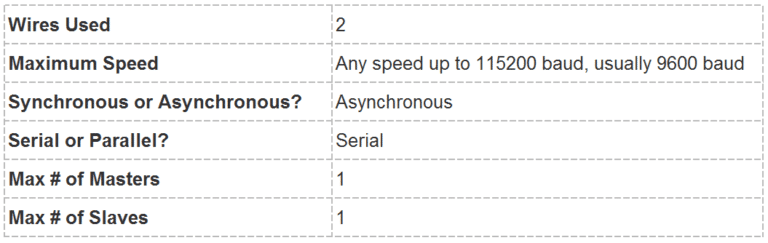
Uses only two wires
-
No clock signal required
-
Includes parity bit for error checking
-
As long as both parties set up the structure of the data packet
-
A well-documented and widely used method
Disadvantages
-
Maximum size of data frame is 9 bits
-
No support for multiple slave systems or multiple master systems
-
Baud rates of each UART must be within 10% of each other
Author Bio: www.cuitbasics.com, a personal website focusing on Raspberry Pi, ARDUINO, and DIY, translated by 吃完饭后不刷牙.
▼ Long press the following image to follow → Automotive ECU Design▼