Introduction: Why Must Embedded Engineers Understand Bootloaders?
When you first enter the field of embedded systems, have you encountered these confusions?After powering on the development board, the serial port shows a blank screen, even though the program has been burned but does not run;You want to add firmware upgrade functionality to your product but don’t know where to start;During an interview, when asked about the “Bootloader startup process,” you can only stammer without articulating the core.In fact, the root of these problems often lies in the “first piece of code” in embedded systems—the Bootloader. It acts like the “startup password” for the device, determining whether the system can start normally and serving as the “bridge” between the underlying hardware and the upper-level software.In this article, we will start with “why it is necessary to learn” and combinethe low-level collaboration of Assembly and C language, a simplifiedSTM32 Bootloader practical example, and then delve intoadvanced customization of U-Boot, thoroughly dissecting the development logic of the Bootloader. Whether you are a beginner or an engineer looking to break through bottlenecks, this content will help you establish a complete knowledge framework.
1. First Understand: What Exactly is a Bootloader?
You can think of embedded devices (like microcontrollers and development boards) as a car—
- Power on = Insert the key and turn the switch;
- Bootloader = The car’s “self-check + startup program”: First check the engine and fuel system (hardware initialization), then ignite (boot OS/application), and also support “system upgrades” (firmware updates);
- Operating system/bare-metal application = The car’s driving function (running code, implementing business logic).
Professional Definition: The Bootloader is thefirst piece of code that runs after the embedded device is powered on, serving as a “bridge” connecting hardware and upper-level software, with the core mission of “making hardware usable and software runnable.”Compared to the BIOS/UEFI on PCs, the Bootloader is more streamlined and customizable— the Bootloader for a microcontroller may only consist of a few hundred lines of code (even implemented in Assembly), while the Bootloader for complex development boards (like U-Boot) can support advanced features such as network upgrades and device tree passing.To better understand the working logic of the Bootloader, I will use a flowchart to illustrate its core startup steps (taking STM32 and similar Cortex-M chips as an example):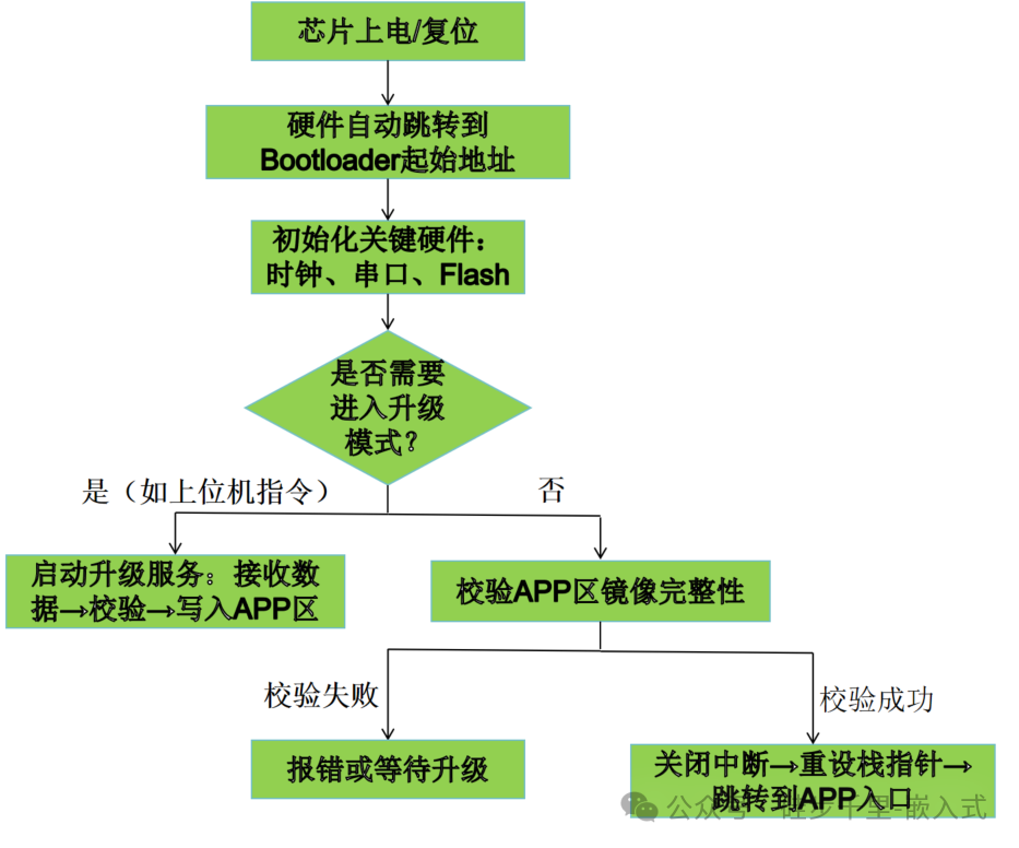
This diagram clearly shows the entire process of the Bootloader from “power on” to “handing over control to the application”:Hardware automatically jumps → Initialization → Determine upgrade needs → Execute upgrade or directly jump. Understanding this process captures the underlying logic of Bootloader design.
2. Why Learn to Write a Bootloader?
- 1. Solve “Startup Issues”: Device powers on with a black screen and no output from the serial port? Most likely, the Bootloader’s hardware initialization was not done correctly (e.g., incorrect clock configuration, stack pointer not set).
- 2. Implement Firmware Upgrades: Does the product need OTA remote upgrades or local serial upgrades? This must rely on the Bootloader to carry the data transfer and Flash writing logic.
- 3. Master Underlying Logic: Understanding the Bootloader = Connecting the “CPU-memory-peripherals” underlying link, directly elevating embedded development skills.
- 4. Enhance Competitiveness: Whether interviewing for an embedded engineer position or developing industrial-grade products, Bootloader development experience is a core advantage.
3. Core Steps of Bootloader Development (From 0 to 1)
Regardless of whether the Bootloader is simple or complex, the development logic revolves around the four steps of “Initialization → Receive Firmware → Write to Flash → Jump to Application“. Below, I will take a simplifiedSTM32 Bootloader as an example (including collaboration between Assembly and C language) to break down the practical details step by step.
Prerequisites
- Hardware: STM32F103 development board (core board is sufficient), USB-TTL serial module, J-Link debugger;
- Software: Keil MDK (for compiling code), SecureCRT (for serial terminal), STM32CubeMX (for assisting in clock configuration).
Step 1: Clarify Requirements
We need to write a Bootloader that “receives firmware via serial and jumps to the application,” with core functionalities:
- Power on initializes the serial port (for receiving firmware) and GPIO (LED indicator);
- Serial port receives the bare-metal application firmware sent from the PC (in HEX format);
- Writes the firmware to a specified address in the STM32’s Flash;
- Jumps to run the application program.
Step 2: Hardware Initialization (Assembly + C Language Combination)
Thefirst stage of the Bootloader must be in Assembly— because after the device is powered on, the RAM has not yet been initialized, and C language requires stack support to run. The core task of this stage is to “set the stage” for the C language to work safely.
Assembly Startup File (Stage 1): start.s
; Assembly file: start.s (First stage of Bootloader)
    AREA    RESET, CODE, READONLY  ; Define read-only code section
    ENTRY                          ; Declare program entry point
    B       Reset_Handler          ; Jump to reset handler after power on
    B       .                      ; Other exceptions (temporarily empty implementation to avoid running away)

Reset_Handler:
    ; 1. Disable global interrupts (to avoid interference during initialization)
    CPSID   I
    ; 2. Initialize stack pointer (SP): The starting address of STM32F103's RAM is 0x20000000, stack size set to 1KB (0x400)
    LDR     SP, =0x20000400
    ; 3. Initialize system clock (HSE 8MHz crystal, multiplied to 72MHz, call C function SystemInit)
    BL      SystemInit
    ; 4. Jump to C main function
    BL      main
    ; 5. Prevent infinite loop after jump failure
Loop:
    B       Loop
END
C Language Initialization (Stage 2): main.c
After Assembly completes the “stage setting,” C language is responsible for specific hardware initialization (serial port, GPIO):
#include "stm32f10x.h"

// Initialize LED (PA0, used to indicate Bootloader status)
void LED_Init(void) {
    GPIO_InitTypeDef GPIO_InitStruct;
    RCC_APB2PeriphClockCmd(RCC_APB2Periph_GPIOA, ENABLE);  // Enable GPIOA clock

    GPIO_InitStruct.GPIO_Pin = GPIO_Pin_0;
    GPIO_InitStruct.GPIO_Mode = GPIO_Mode_Out_PP;         // Push-pull output
    GPIO_InitStruct.GPIO_Speed = GPIO_Speed_50MHz;
    GPIO_Init(GPIOA, &GPIO_InitStruct);

    GPIO_SetBits(GPIOA, GPIO_Pin_0);  // Initially turn on LED (indicating Bootloader is running)
}


void USART1_Init(void) {
    GPIO_InitTypeDef GPIO_InitStruct;
    USART_InitTypeDef USART_InitStruct;

    RCC_APB2PeriphClockCmd(RCC_APB2Periph_USART1 | RCC_APB2Periph_GPIOA, ENABLE);

    // Configure TX pin (PA9) as alternate push-pull output
    GPIO_InitStruct.GPIO_Pin = GPIO_Pin_9;
    GPIO_InitStruct.GPIO_Mode = GPIO_Mode_AF_PP;
    GPIO_InitStruct.GPIO_Speed = GPIO_Speed_50MHz;
    GPIO_Init(GPIOA, &GPIO_InitStruct);

    // Configure RX pin (PA10) as floating input
    GPIO_InitStruct.GPIO_Pin = GPIO_Pin_10;
    GPIO_InitStruct.GPIO_Mode = GPIO_Mode_IN_FLOATING;
    GPIO_Init(GPIOA, &GPIO_InitStruct);

    // Configure serial port parameters
    USART_InitStruct.USART_BaudRate = 9600;
    USART_InitStruct.USART_WordLength = USART_WordLength_8b;
    USART_InitStruct.USART_StopBits = USART_StopBits_1;
    USART_InitStruct.USART_Parity = USART_Parity_No;
    USART_InitStruct.USART_HardwareFlowControl =
    USART_HardwareFlowControl_None;
    USART_InitStruct.USART_Mode = USART_Mode_Rx | USART_Mode_Tx;
    USART_Init(USART1, &USART_InitStruct);

    USART_Cmd(USART1, ENABLE);  // Enable serial port
}

int main(void) {
    LED_Init();
    USART1_Init();
    USART_SendData(USART1, "Bootloader Ready!\r\n");  // Print readiness message to serial port

    // Subsequent steps: receive firmware, write to Flash, jump to application (detailed below)
   while(1);
}
Step 3: Receive Firmware and Write to Flash
The Flash of STM32 needs to be pre-planned for addresses to avoid conflicts with the Bootloader:
- Bootloader Area: 0x08000000 ~ 0x08003FFF (16KB, sufficient to store a minimal Bootloader);
- Application Area: 0x08004000 ~ 0x0801FFFF (112KB, for storing user applications).
Flash Erase and Write Functions
#define APP_ADDR  0x08004000  // Application start address

// Unlock Flash (STM32's Flash is locked by default, must unlock before writing)
void FLASH_Unlock(void) {
    FLASH->KEYR = 0x45670123;  // Unlock key 1
    FLASH->KEYR = 0xCDEF89AB;  // Unlock key 2
}

// Lock Flash
void FLASH_Lock(void) {
    FLASH->CR |= FLASH_CR_LOCK;
}

// Erase the sector where the application is located (the sector size of STM32F103 is 1KB)
void Flash_Erase_APP(void) {
    FLASH_Unlock();
    FLASH->CR |= FLASH_CR_PER;   // Enable page erase
    FLASH->AR = APP_ADDR;        // Set erase address (application start address)
    FLASH->CR |= FLASH_CR_STRT;  // Start erasing
    while (FLASH->SR && FLASH_SR_BSY);  // Wait for erasure to complete
    FLASH->CR &= ~FLASH_CR_PER;  // Disable page erase
    FLASH_Lock();
}

// Write data to Flash (write by word, addr must be word-aligned)
void Flash_Write(uint32_t addr, uint16_t *buf, uint16_t len) {
    FLASH_Unlock();
    FLASH->CR |= FLASH_CR_PG;    // Enable programming
    for (uint16_t i = 0; i < len; i += 2) {  // Write 2 bytes (half-word) at a time
        *(volatileuint16_t*)(addr + i) = buf[i/2];
        while (FLASH->SR && FLASH_SR_BSY);  // Wait for writing to complete
    }
    FLASH->CR &= ~FLASH_CR_PG;   // Disable programming
    FLASH_Lock();
}
Serial Port Firmware Reception Logic
// Receive firmware via serial (assuming fixed-length binary data, actual need to parse HEX)
void USART_Receive_Firmware(void) {
uint16_t firmware_buf[512];  // Reception buffer (512 words = 1024 bytes)
uint16_t len = 0;

    USART_SendData(USART1, "Waiting for Firmware...\r\n");

    // Loop to receive data (actual need to add timeout check)
    while(1) {
      if(USART_GetFlagStatus(USART1, USART_FLAG_RXNE) == SET) {
          firmware_buf[len++] = USART_ReceiveData(USART1);  // Read data
          // Assume receiving 1024 bytes (actual need to determine based on firmware size)
          if(len >= 512) {  // 512 words = 1024 bytes
               USART_SendData(USART1, "Receive Complete! Writing Flash...\r\n");
                Flash_Erase_APP();  // Erase old application
                Flash_Write(APP_ADDR, firmware_buf, len);  // Write new application
                USART_SendData(USART1, "Write Complete!\r\n");
                break;
            }
        }
    }
}
Step 4: Jump to Application Program
After writing the firmware, the Bootloader needs to “hand over control” to the application. The core is toset the application’s stack pointer (SP) and jump to the application entry address (PC).
Jump Function Implementation
// Define application function pointer type (pointing to a function with no parameters and no return value)
typedef void(*AppFunc)(void);

void Jump_To_App(void) {
    AppFunc app_start;

    // Application's stack pointer (stored at APP start address)
    uint32_t app_stack = *(volatileuint32_t*)APP_ADDR;

    // Check if the application exists (stack pointer must be within valid RAM range: 0x20000000~0x20004000)
    if ((app_stack > 0x20000000) && (app_stack < 0x20004000)) {

        // Application entry address (start address + 4)
        app_start = (AppFunc)*(volatileuint32_t*)(APP_ADDR + 4);
        __set_MSP(app_stack);  // Set main stack pointer (MSP) to the application's stack pointer
        app_start();           // Jump to application
    } else {
        USART_SendData(USART1, "No App Found!\r\n");
    }
}

// Complete main function
int main(void) {
    LED_Init();
    USART1_Init();
    USART_SendData(USART1, "Bootloader Ready!\r\n");

    USART_Receive_Firmware();  // Receive firmware
    GPIO_ResetBits(GPIOA, GPIO_Pin_0);  // Turn off LED (indicating Bootloader has completed its task)
    Jump_To_App();             // Jump to application

    while(1);  // Infinite loop if jump fails
}
Step 5: Compile and Burn Test
- 1. Compile Bootloader: Use Keil MDK to compile start.s and main.c, generating a .hex file;
- 2. Burn Bootloader: Use J-Link to burn the .hex file to the STM32 at address 0x08000000;
- 3. Write Test Application: Write a simple LED blinking program (e.g., toggle PA1 every 500ms), set “start address to 0x08004000” during compilation;
- 4. Send Firmware via Serial: Use SecureCRT to open the serial port (9600 baud rate) and send the binary data of the application;
- 5. Observe Phenomenon: LED lights up (Bootloader running) → After receiving completes, LED turns off → Application’s LED starts blinking, indicating successful jump!
4. Advanced Practice: U-Boot Customization
If your device is an ARM-Linux development board (like IMX6, Raspberry Pi) and requires a more powerful Bootloader, it is recommended to customize based onU-Boot (the mainstream in the industry). The core steps are:
- 1. Download Source Code: Download the corresponding version from the U-Boot official website (https://www.denx.de/wiki/U-Boot/);
- 2. Configure Compilation:
# Configure target board (taking IMX6ULL as an example) make mx6ull_14x14_evk_defconfig # Compile (using cross-compiler) make -j4 CROSS_COMPILE=arm-linux-gnueabihf- - 3. Add Custom Features:
- Add a serial upgrade command: Add
<span>cmd/myupdate.c</span>in the<span>cmd/</span>directory to support firmware reception; - Adapt device tree: Modify the device tree files under
<span>arch/arm/dts/</span>to match the hardware’s serial and Flash configurations;
<span>u-boot.imx</span> to an SD card, insert it into the development board to boot, and execute commands via the serial terminal (e.g.,<span>tftp 0x80008000 zImage</span> to load the Linux kernel).5. Development Pitfall Guide
- 1. Address Conflicts: The addresses of the Bootloader and application must be offset; during compilation, clearly set the “start address” and “size” in Keil/U-Boot;
- 2. Flash Unlocking: STM32’s Flash is locked by default; you must call
<span>FLASH_Unlock()</span>before writing, otherwise writing will fail; - 3. Stack Pointer Settings: When jumping to the application, you must use the application’s stack pointer (stored at the APP start address), not the Bootloader’s stack;
- 4. Serial Baud Rate: The baud rate of the Bootloader and the PC’s serial port must match (e.g., 9600), otherwise data cannot be received;
- 5. Debugging Tips: Use J-Link to step through the Assembly code to locate hardware initialization errors; use serial port printing logs to track the firmware reception and writing process.
Conclusion: Suggested Learning Path for Bootloaders
From beginner to expert, I recommend a gradual approach:
- Beginner: Complete a minimal Bootloader using STM32 (serial reception + jump), mastering the core process of “Assembly initialization → C language hardware configuration → Flash operations → Jump”;
- Intermediate: Implement HEX file parsing, timeout retransmission, firmware verification (like CRC32), and improve upgrade functionality;
- Advanced: Customize based on U-Boot, adapt to Linux systems, and implement network upgrades and device tree passing;
- Practical: Combine OTA technology to develop an industrial-grade Bootloader that supports remote upgrades.
Bootloaders may seem complex, but the core logic remains consistent— as long as you can connect the four key links of “hardware initialization → data reception → Flash operations → program jump,” you can easily handle various scenarios. If you encounter problems during practical operations, feel free to leave a comment for discussion, or you can message me for the complete code and debugging tutorial.~Finally, I wish everyone can thoroughly understand Bootloaders and progress further in the field of embedded development!