Through software development with IO and serial ports, we have already experienced embedded software development. I wonder if anyone is puzzled about why software can control hardware? I certainly had this question when I was learning about the 51 microcontroller. Today, let’s pause software development and analyze how microcontrollers achieve the integration of software and hardware. We will also analyze the compilation and execution of a basic microcontroller program.
Integration of Software and Hardware
Beginners often have a confusion: why can software control hardware? For example, when programming the 51 microcontroller, why can we output high and low levels on the IO port just by writing P1=0X55? To clarify this question, we first need to understand a concept: Address Space.
Addressing Space
What is address space? The so-called address space is the addressing range of the PC pointer, hence it is also called addressing space.
As we all know, our computers have 32-bit and 64-bit systems. Why is that? Because in a 32-bit system, the PC pointer is a 32-bit binary number, which is 0xffffffff, and the range is only 4G of addressing space. Now that memory is getting larger, 4G is simply not enough, so it needs to be expanded. To access memory beyond the 4G range, a 64-bit system was created. What about STM32? It is 32-bit, so the PC pointer is also 32-bit, and the addressing space is 4G.
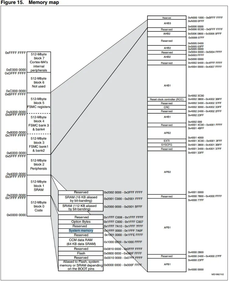
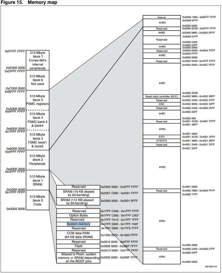
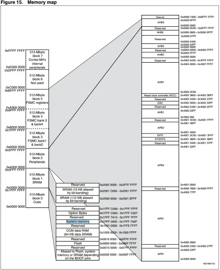
Let’s take a look at the addressing space of STM32. In the data sheet “STM32F407_Data_Sheet.pdf”, there is a diagram that shows the addressing space allocation of STM32. All chips will have this diagram, usually called the Memory map. When using a new chip, always check this diagram first.
-
On the far left, there are 8 blocks, each 512M, totaling 4G, which is the chip’s addressing space.
-
Block 0 contains a section called FLASH, which is the internal FLASH where our program is downloaded, starting at address 0X800 0000. Note that this only has 1M of space. Now STM32 has chips with 2M flash. Where does the FLASH beyond 1M go? Please refer to the corresponding chip manual.
-
In block 1, there are two segments of SRAM totaling 128K, which is the memory we mentioned earlier, used to store variables used by the program. If needed, the program can also run from SRAM. Isn’t the 407 supposed to have 196K?
-
Actually, the 407 has 196K of memory, but 64K is not ordinary SRAM; it is located in block 0’s CCM. These two areas are not contiguous, and CCM can only be used by the core; peripherals cannot use CCM memory, otherwise, it will crash.
-
Block 2 is for Peripherals, which is the peripheral space. On the right, it mainly consists of APB1/APB2, AHB1/AHB2. What are these? We will discuss that later.
-
Blocks 3, 4, and 5 are for FSMC space, which can expand to external SRAM, NAND FLASH, LCD, and other peripherals.
Now that we have analyzed the addressing space, let’s go back and see how software controls hardware. In the example of outputting to the IO port, we configure the IO port by calling library functions. Let’s see how the library function does this.
For example:
GPIO_SetBits(GPIOG, GPIO_Pin_0 | GPIO_Pin_1 | GPIO_Pin_2| GPIO_Pin_3);
This function actually assigns a value to a variable, specifically to the member BSRRL of the GPIOx structure.
void GPIO_SetBits(GPIO_TypeDef* GPIOx, uint16_t GPIO_Pin)
{
 /* Check the parameters */
 assert_param(IS_GPIO_ALL_PERIPH(GPIOx));
 assert_param(IS_GPIO_PIN(GPIO_Pin));

 GPIOx->BSRRL = GPIO_Pin;
}
assert_param: This is an assertion used to check whether the input parameters meet the requirements. GPIOx is an input parameter, which is a pointer to a GPIO_TypeDef structure, so we use -> to access its members.
GPIOx is the parameter we passed, GPIOG. What exactly is it? It is defined in stm32f4xx.h.
#define GPIOG ((GPIO_TypeDef *) GPIOG_BASE)
GPIOG_BASE is also defined in the file as follows:
#define GPIOG_BASE           (AHB1PERIPH_BASE + 0x1800)
AHB1PERIPH_BASE, AHB1 address, is starting to make sense, right? Let's take a closer look.

/*!< Peripheral memory map */
#define APB1PERIPH_BASE       PERIPH_BASE
#define APB2PERIPH_BASE       (PERIPH_BASE + 0x00010000)
#define AHB1PERIPH_BASE       (PERIPH_BASE + 0x00020000)
#define AHB2PERIPH_BASE       (PERIPH_BASE + 0x10000000)
Now let’s find the definition of PERIPH_BASE.
#define PERIPH_BASE ((uint32_t)0x40000000) At this point, we can see that operating on IO port G is actually manipulating a member of a structure at the address 0X40000000+0X1800. In other words, we are manipulating the registers at this location. Essentially, it is the same as operating on a normal variable, as shown in the two lines of code below, the difference being that variable i is at the SRAM space address, while 0X40000000+0X1800 is at the peripheral space address.
u32 i;
i = 0x55aa55aa;
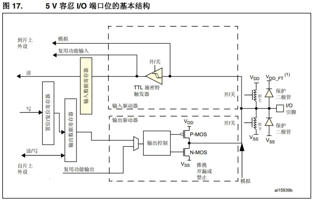
The register at this peripheral space address is part of the IO port hardware. As shown in the figure, the output data register on the left is the register (memory, variable) we are manipulating, and its address is 0X40000000+0X1800+0x14.
Controlling other peripherals is similar; it involves writing data to the peripheral registers, just like manipulating memory, to control the peripherals.
Registers should actually be referred to as memory in general; peripheral registers should be called special registers. Gradually, everyone started calling peripherals registers, while others are referred to as memory or RAM. Why can registers control hardware peripherals? Because, roughly speaking, a BIT in a register is like a switch, ON is 1, OFF is 0. By using this electronic switch to control the circuit, we can control the peripheral hardware.
Pure Software – A Comprehensive Small Program
We have completed the control of serial ports and IO ports, but we only know how to use them, with no knowledge of the underlying workings. How does the program run? Where is the code stored? How is memory preserved? Next, we will learn the basic elements of embedded software through a simple program.
Analyzing Startup Code
-
Where does the function start running?
Every chip has a reset function. After a reset, the chip’s PC pointer (a register that indicates the program’s running position; for multi-stage pipeline chips, the PC may not align with the actual instruction execution position, but for now, we will assume they align) resets to a fixed value, usually 0x00000000. In STM32, it resets to 0X08000004. Therefore, the first code executed after a reset is at 0X08000004. Earlier, we copied a startup code file into the project, right? The file startup_stm32f40_41xxx.s is called startup code because the assembly program inside is the program executed after the reset. In the file, there is a data table called interrupt vector, which contains the execution addresses of various interrupts. Reset is also an interrupt.
When the chip resets, it loads the value of Reset_Handler ( a function pointer) from the interrupt table into the PC pointer, and the chip will execute the Reset_Handler function. ( A function entry is a pointer)
; Vector Table Mapped to Address 0 at Reset
                AREA    RESET, DATA, READONLY
                EXPORT  __Vectors
                EXPORT  __Vectors_End
                EXPORT  __Vectors_Size

__Vectors       DCD     __initial_sp               ; Top of Stack
                DCD     Reset_Handler              ; Reset Handler
                DCD     NMI_Handler                ; NMI Handler
                DCD     HardFault_Handler          ; Hard Fault Handler
                DCD     MemManage_Handler          ; MPU Fault Handler
                DCD     BusFault_Handler           ; Bus Fault Handler
                DCD     UsageFault_Handler         ; Usage Fault Handler
The Reset_Handler function first executes the SystemInit function, which is in the standard library and mainly initializes the chip clock. Then it jumps to __main to execute. What is the __main function?
Is it the main function we defined in main.c? We will discuss this later.
; Reset handler
Reset_Handler    PROC
                 EXPORT  Reset_Handler             [WEAK]
        IMPORT  SystemInit
        IMPORT  __main

                 LDR     R0, =SystemInit
                 BLX     R0
                 LDR     R0, =__main
                 BX      R0
                 ENDP
How does the chip know to execute the startup code first? Or how do we place this startup code at the reset position? This involves a file that is generally not focused on, called wujique.sct, located in the wujique\prj\Objects directory. This file is usually called a scatter loading file, and during linking, the compiler uses this file to place various code segments and variables.
In the MDK software, you can find settings related to this in the Options menu under Linker.
Uncheck the box for Use Memory Layout from Target Dialog, and previously unmodifiable boxes will now be editable. Click Edit to make changes.
The code editing box will display the contents of the scatter loading file, which currently only contains basic content.
This file is very powerful; by modifying it, you can configure many features of the program, such as: 1. Specifying the size and starting position of FLASH and RAM. When we divide the program into BOOT, CORE, APP, or even separate drivers, this can be useful. 2. Specifying the location of functions and variables, such as loading functions to run in RAM.
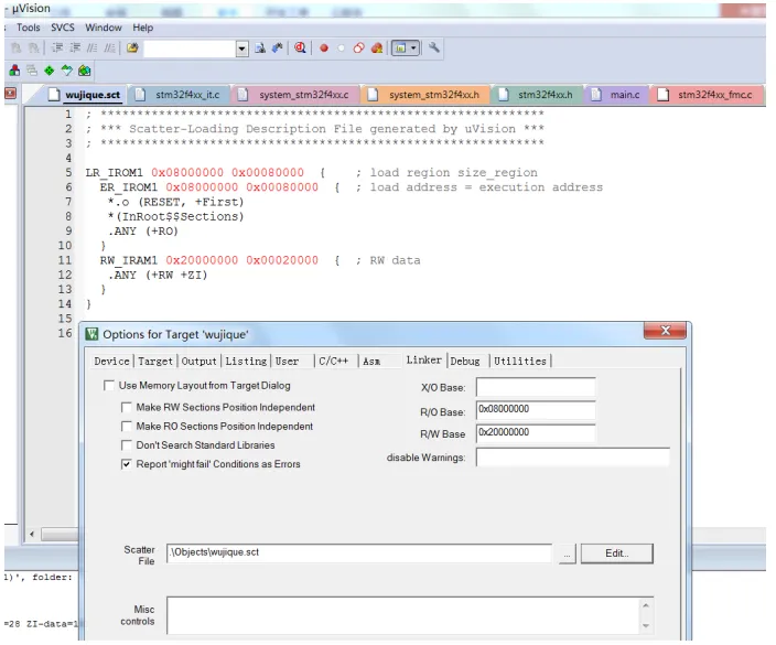
From this basic scatter loading file, we can see:
-
Line 6 defines ER_IROM1, which is our internal FLASH, starting at 0x08000000, with a size of 0x00080000.
-
Line 7 .o (RESET, +First) starts placing an .o file from 0x08000000, and specifies that the RESET block should be placed first using (RESET, +First). What is the RESET block? Please refer to the startup code; the interrupt vector is an AREA named RESET, which is READONLY. This way, after compilation, the RESET block will be placed at 0x08000000, meaning the interrupt vector will be located there. DCD allocates space, 4 bytes, the first being __initial_sp, and the second being the pointer to the Reset_Handler function. In other words, the compiled program will place the pointer (address) of the Reset_Handler function at 0x800000+4. Therefore, when the chip resets, it can find the reset function Reset_Handler.
-
Line 8 *(InRoot$$Sections) What is this? GOOGLE it! We will discuss it later.
-
Line 9 .ANY (+RO) means all other RO sections will be placed afterwards. This means that other code will follow the startup code.
-
Line 11 RW_IRAM1 0x20000000 0x00020000 defines the size of RAM.
-
Line 12 .ANY (+RW +ZI) specifies that all RW and ZI variables will be placed in RAM. RW and ZI refer to variables, and this line specifies where the variables will be stored.
Analyzing User Code
At this point, the basic startup process has been analyzed. Next, we will analyze user code, starting with the main function. 1. After the program jumps to the main function: RCC_GetClocksFreq retrieves the RCC clock frequency; SysTick_Config configures SysTick, enabling the SysTick interrupt every 10 milliseconds.
Delay(5); introduces a delay of 50 milliseconds.
int main(void)
{
GPIO_InitTypeDef GPIO_InitStructure;
/*!< At this stage the microcontroller clock setting is already configured,
this is done through SystemInit() function which is called from startup
files before to branch to application main.
To reconfigure the default setting of SystemInit() function,
refer to system_stm32f4xx.c file */
/* SysTick end of count event each 10ms */
RCC_GetClocksFreq(&RCC_Clocks);
SysTick_Config(RCC_Clocks.HCLK_Frequency / 100);
/* Add your application code here */
/* Insert 50 ms delay */
Delay(5);
}2. The initialization of IO is not discussed here; we enter while(1), which is an infinite loop. Embedded programs are always in an infinite loop; otherwise, they will run away.
/* Initialize LED IO port */
RCC_AHB1PeriphClockCmd(RCC_AHB1Periph_GPIOG, ENABLE);

GPIO_InitStructure.GPIO_Pin = GPIO_Pin_0 | GPIO_Pin_1 | GPIO_Pin_2| GPIO_Pin_3;
GPIO_InitStructure.GPIO_Mode = GPIO_Mode_OUT;

GPIO_InitStructure.GPIO_OType = GPIO_OType_PP;
GPIO_InitStructure.GPIO_Speed = GPIO_Speed_100MHz;
GPIO_InitStructure.GPIO_PuPd = GPIO_PuPd_UP;
GPIO_Init(GPIOG, &GPIO_InitStructure);

/* Infinite loop */
mcu_uart_open(3);
while (1)
{
  GPIO_ResetBits(GPIOG, GPIO_Pin_0|GPIO_Pin_1|GPIO_Pin_2|GPIO_Pin_3);
  Delay(100);
  GPIO_SetBits(GPIOG, GPIO_Pin_0|GPIO_Pin_1|GPIO_Pin_2|GPIO_Pin_3);
  Delay(100);
  mcu_uart_test();

  TestFun(TestTmp2);
}
3. Inside the while(1) loop, the TestFun function is called, which uses two global variables and two local variables.
/* Private functions ---------------------------------------------------------*/
u32 TestTmp1 = 5;// Global variable, initialized to 5
u32 TestTmp2;// Global variable, uninitialized

const u32 TestTmp3[10] = {6,7,8,9,10,11,12,13,12,13};

u8 TestFun(u32 x)// Function with one parameter, returning a u8 value
{
 u8 test_tmp1 = 4;// Local variable, initialized
 u8 test_tmp2;// Local variable, uninitialized

static u8 test_tmp3 = 0;// Static local variable

 test_tmp3++;

 test_tmp2 = x;

if(test_tmp2> TestTmp1)
  test_tmp1 = 10;
else
  test_tmp1 = 5;

 TestTmp2 +=TestTmp3[test_tmp1];

return test_tmp1;
}
Then the program continues executing in the while loop of the main function. What about interrupts? Yes, interrupts interrupt the normal execution flow of the program. Interrupts are the normal execution flow interruptions. Let’s check the Delay function; if uwTimingDelay is not equal to 0, it will wait indefinitely? Who will set uwTimingDelay to 0?
/**
  * @brief  Inserts a delay time.
  * @param  nTime: specifies the delay time length, in milliseconds.
  * @retval None
  */
void Delay(__IO uint32_t nTime)
{
  uwTimingDelay = nTime;

  while(uwTimingDelay != 0);
}
Search for the uwTimingDelay variable. The function TimingDelay_Decrement will decrement the variable until it reaches 0.
/**
  * @brief  Decrements the TimingDelay variable.
  * @param  None
  * @retval None
  */
void TimingDelay_Decrement(void)
{
  if (uwTimingDelay != 0x00)
  {
    uwTimingDelay--;
  }
}
Where is this function executed? Upon searching, it runs in the SysTick_Handler function. Who uses this function?
/**
  * @brief  This function handles SysTick Handler.
  * @param  None
  * @retval None
  */
void SysTick_Handler(void)
{
  TimingDelay_Decrement();
}
Upon searching, this function is present in the interrupt vector table, meaning that the function pointer is stored in the interrupt vector table. When an interrupt occurs, this function will be executed. Of course, there will be operations to save and restore the context when entering and exiting interrupts. This mainly involves assembly, which we will not analyze for now. If interested, you can research it yourself. Typically, we do not need to worry about context switching when developing programs now.
__Vectors       DCD     __initial_sp               ; Top of Stack
                DCD     Reset_Handler              ; Reset Handler
                DCD     NMI_Handler                ; NMI Handler
                DCD     HardFault_Handler          ; Hard Fault Handler
                DCD     MemManage_Handler          ; MPU Fault Handler
                DCD     BusFault_Handler           ; Bus Fault Handler
                DCD     UsageFault_Handler         ; Usage Fault Handler
                DCD     0                          ; Reserved
                DCD     0                          ; Reserved
                DCD     0                          ; Reserved
                DCD     0                          ; Reserved
                DCD     SVC_Handler                ; SVCall Handler
                DCD     DebugMon_Handler           ; Debug Monitor Handler
                DCD     0                          ; Reserved
                DCD     PendSV_Handler             ; PendSV Handler
                DCD     SysTick_Handler            ; SysTick Handler
Remaining Questions
1. What is the __main function? Is it the main function we defined in main.c? 2. What is *(InRoot$$Sections) in the scatter loading file? 3. When is the ZI section, which is the zero-initialized data section, initialized? Who initializes it?
Why were these questions left unanswered earlier? Because they are all related! Follow the clues!
Understanding Code Composition through MAP Files
Compilation Results
After compiling the program, information will be output in the Build Output window below:
*** Using Compiler 'V5.06 update 5 (build 528)', folder: 'C:\Keil_v5\ARM\ARMCC\Bin'
Build target 'wujique'
compiling stm32f4xx_it.c...
...
assembling startup_stm32f40_41xxx.s...
compiling misc.c...
...
compiling mcu_uart.c...
linking...
Program Size: Code=9038 RO-data=990 RW-data=40 ZI-data=6000
FromELF: creating hex file...
".\Objects\wujique.axf" - 0 Error(s), 0 Warning(s).
Build Time Elapsed:  00:00:32
- The build target is wujique.
- C files are compiling, assembly files are assembling; this process is called compilation.
- After compilation, linking occurs.
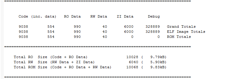
- Finally, we obtain a compilation result: 9038 bytes of code, 990 bytes of RO data, 40 bytes of RW data, and 6000 bytes of ZI data. CODE is the code, which is easy to understand; what are RO, RW, and ZI?
- FromELF creates a hex file; FromELF is a useful tool that needs to be added to the options to use.
MAP File Configuration
More specific compilation information is in the map file. In MDK Options, we can see that all information is stored in \Listings\wujique.map
By default, many compilation information options may not be checked; checking all options will increase compilation time.
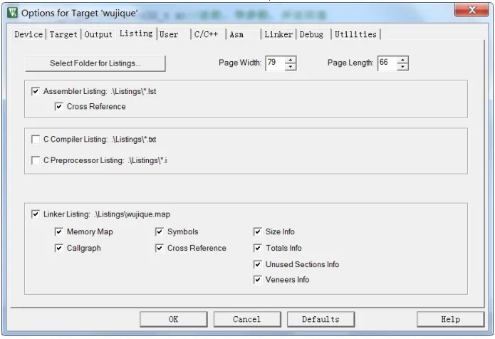
MAP File
Open the map file; it looks chaotic? You will get used to it. We will focus on the key points.
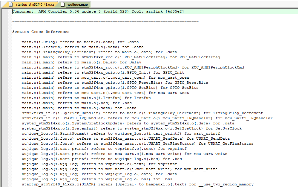
-
Overall information from the map
Starting from the end , did you see? The last section of the map content describes the basic overview of the entire program.
How much RO? What exactly is RO?
How much RW? What is RW?
Why does ROM not include ZI Data? Why does it include RW Data?
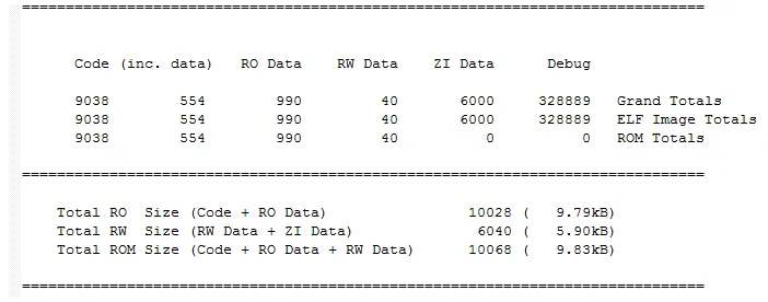
-
Image Component Sizes
Looking up, we see Image component sizes, which is more detailed than the overall statistics.
This part of the content describes the overview of each source file.
First, it is our own source code; this program has little code, only main.o, wujique_log.o, and some other STM32 library files.
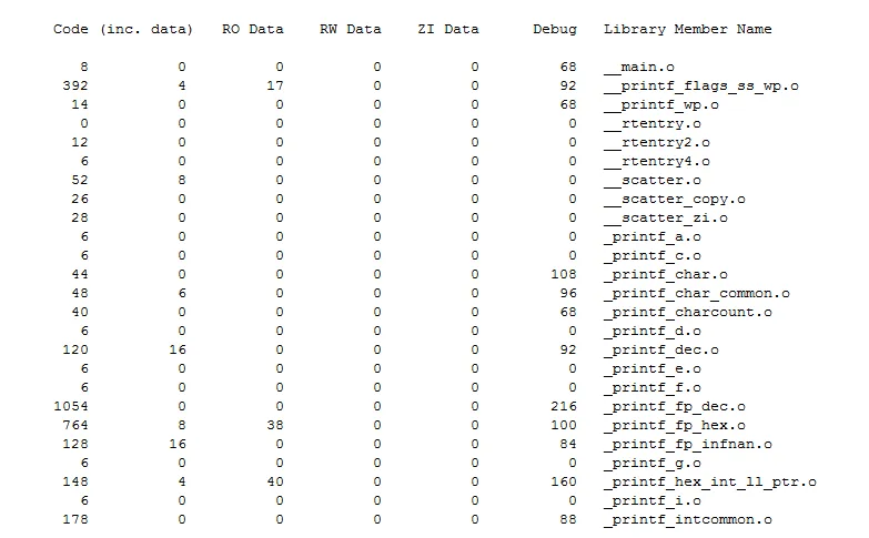
The second part is the files in the library; did you see? There is a main.o. Is the main function our defined main function? Obviously not; our main function is in the main.o file. In such a small project, so many libraries are used; have you ever paid attention to this? Probably not, unless you have previously compressed a program originally on 1M flash to run on 512K.
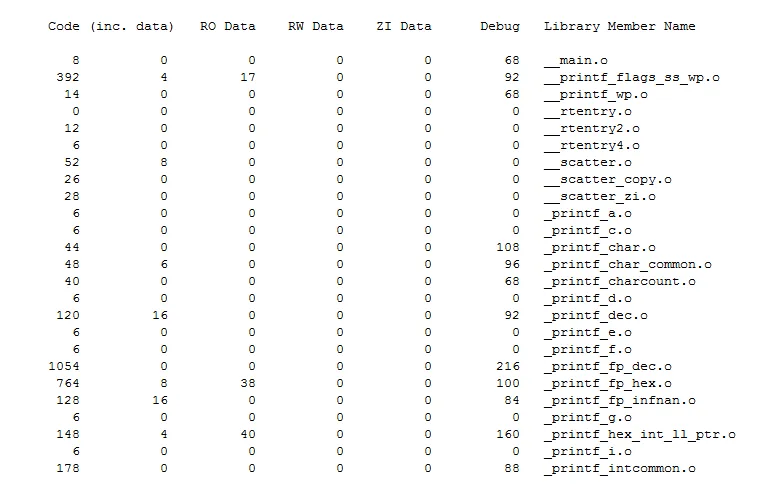
The third part is also from the library, which we have not analyzed yet.
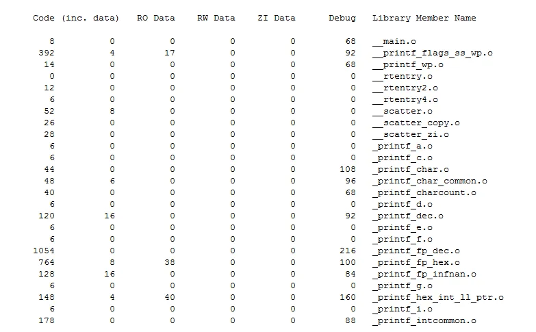
What are library files? Library files are code libraries that others have already written. In the code, we often include some header files, for example:
#include <stdarg.h>
#include <stdlib.h>
#include <string.h>
These are the header files of the library. These header files are stored in the installation directory of the MDK development tool. The library functions we often use include: memcpy, memcmp, strcmp, etc. As long as the code includes these functions, the library files will be linked.
-
File MAP
Further up is the file MAP, which shows the location of each file’s code segments (functions) and variables in ROM and RAM. First, in ROM at 0x08000000, the RESET from startup_stm32f40_41xxx.o is indeed placed there.
What are library files?
Library files are code libraries that others have already written.
In the code, we often include some header files, for example:
#include <stdarg.h>
#include <stdlib.h>
#include <string.h>
These are the header files of the library. These header files are stored in the installation directory of the MDK development tool.
The library functions we often use include:
memcpy, memcmp, strcmp, etc.As long as the code includes these functions, the library files will be linked.
-
File MAP
Further up is the file MAP, which shows the location of each file’s code segments (functions) and variables in ROM and RAM. First, in ROM at 0x08000000, the RESET from startup_stm32f40_41xxx.o is indeed placed there.
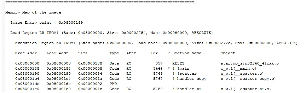
Each file has multiple lines, for example, the serial port has four functions.

Then for RAM, the variables in main.o are placed at 0x20000000, totaling 0x0000000c, with types Data and RW. The serial port has two types of variables, data and bss. What is bss? These two names are section names, meaning segments. Looking at the previous type and Attr,
RW Data is placed in the .data segment; RW Zero is placed in the .bss segment. RW Zero is actually ZI. Which variables are RW and which are ZI?
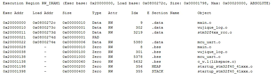
At this point, we can explain the following concepts:
Code refers to the code and functions.
RO Data refers to read-only variables, such as arrays modified with const.
RW Data refers to read-write variables, such as global variables and static local variables.
ZI Data refers to read-write variables that are automatically initialized to 0, mostly arrays, placed in the bss segment.
RO Size equals code plus read-only variables.
RW Size equals read-write variables (including those automatically initialized to 0), which is the size of RAM.
ROM Size is the size of the target file after compilation, which is the size of FLASH. But why? Why does it include RW Data? Because all global variables need an initialization value (even if not truly initialized, the system will allocate an initialization space). For example, if we define a variable u8 i = 8; this global variable, 8, needs to be stored in the FLASH area.
Let’s take a look at the functions; earlier we had a question: Is __main the same function as main? Upon searching for main, we find that main is indeed main, located at 0x08000579.

main is main, located at 0x08000189.

What happened between __main and main? Remember that line in the scatter loading file?
*(InRoot$$Sections)
__main is within this section. The following image shows the address of __main, at 0x08000189. __Vectors is the interrupt vector, placed at the very beginning.
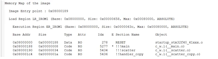
In the scatter loading file, right after RESET is *(InRoot$$Sections).
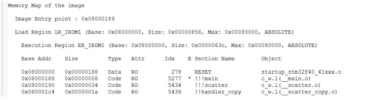
Moreover, the RESET section is exactly 0x00000188 in size.
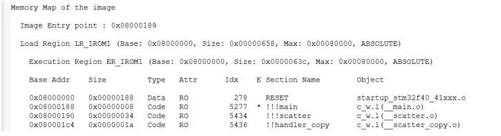
Coincidence? Refer to the PPT document “ARM Embedded Software Development.ppt” or Google it yourself.
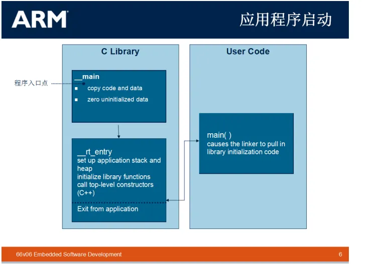
What functionality does this segment of code accomplish? It mainly initializes the ZI code, which means initializing a portion of RAM to 0. Other environment initializations… Typically, we do not need to worry about this part.
-
Others Further up are other information, such as what optimizations were made and which functions were removed.
Conclusion
At this point, we have a basic impression of how a program is composed and how it runs. However, there will be further detailed explanations regarding interrupts.

Part of the electronic book screenshots

【Complete Set of Hardware Learning Materials】