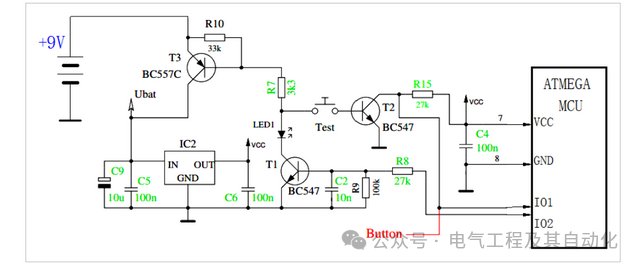
This article introduces the working principle of a classic microcontroller power circuit, as shown in the figure below.
Initial State (Power Off)
Before the circuit is powered on, the “TEST” switch is open, and the MCU is not powered by VCC. At this time, the base of transistor T1 is grounded through R9 (100k), keeping it in the cutoff state. Since both the TEST switch and transistor T1 provide an open circuit, the base of T3 cannot be pulled low, thus T3 also remains in the cutoff state. The +9V power supply is isolated by T3 and does not reach the voltage regulator IC2, so the VCC output remains low.
Startup and Latching
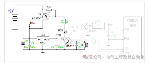
Pressing the “TEST” button starts the circuit. This action provides a grounding path for the base of T3 through R7 and the switch, causing T3 to turn on. Then, the +9V power supply flows through T3 to the voltage regulator IC2, which outputs VCC to power the MCU. After the MCU runs, its IO2 pin outputs a high level. This signal flows through R8, turning on T1. Now, even after releasing the TEST button, there is a path through R7, LED1, and T1 to ground for the base of T3, forming a self-latching mechanism that keeps the circuit powered on.
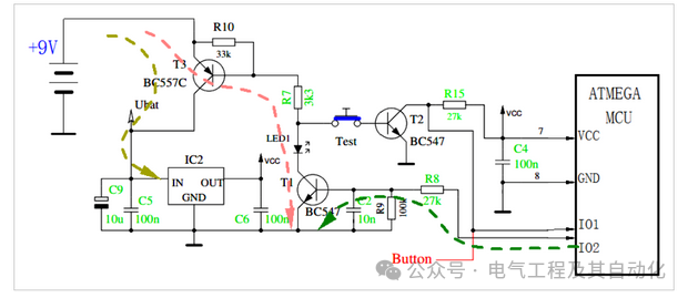
Press TEST to start the circuit
The MCU provides base voltage to T1 to keep T3 on
Software Control Shutdown
To turn off the circuit, the MCU software can set the IO2 pin to a low level. This will turn off T1, subsequently cutting off T3, thus disconnecting the power supply to the system. The MCU can also read the status of the TEST button through the IO1 port to determine if the user has pressed it. For example, after detecting that the user has pressed and released the TEST button, the software can be programmed to turn off the power by setting IO2 to a low level. This feature also allows for functions such as automatic shutdown delays to save power.