This example demonstrates how to use the STM32 microcontroller to build a traffic intersection management system. Traffic intersection management refers to the system methods and strategies used to effectively control and regulate the traffic flow at multiple road intersections. It involves implementing various technologies, techniques, and traffic control measures to ensure the safe and efficient movement of vehicles, pedestrians, and other road users. The main objectives of traffic intersection management include optimizing traffic flow, minimizing congestion, reducing delays, enhancing safety, and improving overall transportation efficiency. This involves coordinating vehicle movements through the use of traffic signals, signage, lane markings, and other control devices.
<em><span><span>Implementation of STM32 Microcontroller:</span></span></em>
This intersection is controlled by four traffic lights. The names of the lights and buttons are as follows: Ri, Ji, and Vi: lights for controlling straight and right-turning traffic. RGi, JGi, and VGi: lights for controlling left-turning traffic.It is important to note that a lit red light indicates that vehicles must stop. A lit yellow light indicates that vehicles should prepare (to stop or proceed with caution), and a lit green light indicates that vehicles have the right of way. A 7-segment display is used to show a cycle of 0-10 seconds, which is used for transitioning between phases. All inputs/outputs are digital.
STM32CubeMX Configuration:
Open CubeMX and create a new project, select the target MCU STM32F401VET and double-click its name.
- Go to the clock configuration and set the system clock to 8MHz.
<strong><span><span>Pin Configuration</span></span></strong><span><span>:</span></span>
- Configure GPIO pins [PB15, PB0, PB1] and [PB2..PB4] as outputs for (R1, J1, V1) and (RG1, JG1, VG1);
- Configure GPIO pins [PB5..PB7] and [PB8..PB10] as outputs for (R2, J2, V2) and (RG2, JG2, VG2);
- Configure GPIO pins [PB12..PB14] and [PC10..PB12] as outputs for (R3, J3, V3) and (R4, J4, V4).
<strong><span><span>Display</span></span></strong><span><span> Pin Configuration</span></span><span><span>:</span></span>
- Configure GPIO pins [PA1..PA6] for the 7-segment display.
- Generate initialization code and open the project in Keil.
- Write application layer code and compile to generate the executable file.
Proteus Configuration:
- Open Proteus and create a new project, draw the schematic.
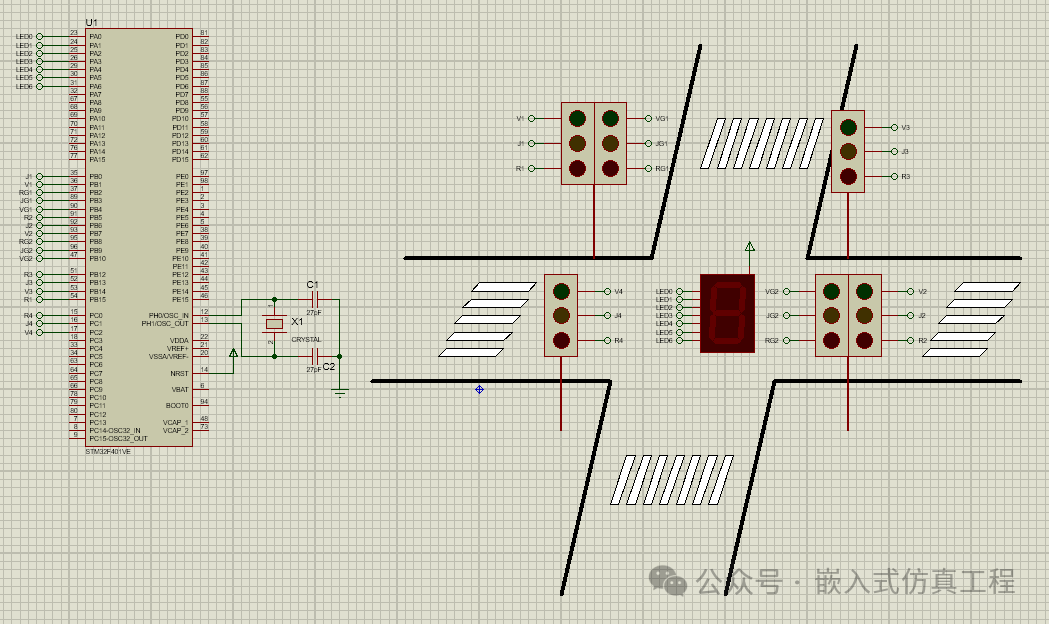 Double-click the STM32 chip module, load the executable file generated by Keil, run the simulation, and the effect is as shown in the figure.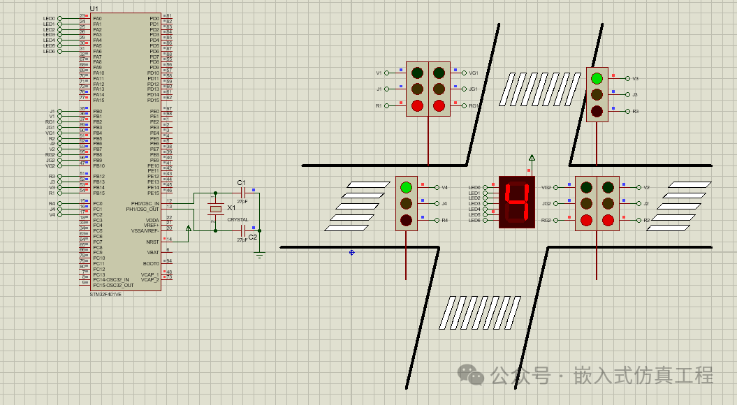
Follow me by clicking the blue text at the top “Embedded Simulation Engineering” or long press to identify the QR code to follow.
Reply in the public account
JTD01
You will receive an automatic reply with the download link for this project.