November 24, 2025
01
Mobile Repair Expert Liang Ge
-
Keeping up with technology trends, delivering the latest updates in the digital field daily, and sharing repair knowledge.
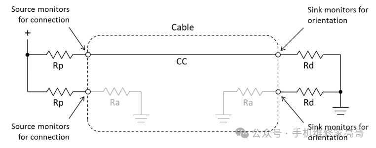
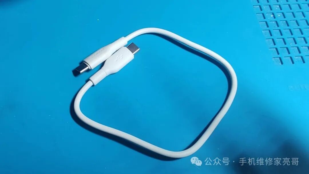
The core of Type-C to Type-C connection isthe negotiation of the master-slave roles through the CC pins (who is the power supply/data host, and who is the power receiver/data slave), and then establishing power, data, and video links based on the negotiation results, compatible with multiple scenarios such as charging, data transmission, and screen projection.
1. Clarifying Two Key Premises
- The “Symmetry” Advantage of Type-C Interface allows for no distinction between front and back, with CC1 and CC2 pins (core negotiation pins) on both sides, eliminating the need to differentiate between “male/female direction”; just plug it in to communicate.
- Definition of Master and Slave Devices
- Master Device (Source/Host): Provides power (power supply) or acts as a data host (e.g., computer, charger, mobile phone in “reverse charging mode”);
- Slave Device (Sink/Device): Receives power (power receiver) or acts as a data slave (e.g., mobile phone, tablet, headphones, external hard drive).
2. Core Principle: “Role Negotiation” of CC Pins (The Most Critical Step)
The CC pins (Configuration Channel) of the Type-C interface act as the “master-slave negotiator”, determining each other’s roles throughresistor matching, a process akin to a “handshake dialogue”, as follows:
1. Both Parties’ “Identity Identification”: Resistor Configuration
- Master Device (Power Supply/Host): The CC pin is connected in series with a pull-up resistor Rp (common values: 56kΩ, 10kΩ, with different values corresponding to different power capabilities), and connected to its own VBUS (positive power);
- Slave Device (Power Receiver/Slave): The CC pin is connected in series with a pull-down resistor Rd (fixed at 5.1kΩ, industry standard), and connected to GND (ground).
2. Negotiation Process (Completed in 3 Quick Steps)
① Physical Connection: The Type-C cable is inserted into the master and slave devices, and the CC pins of both parties are connected through the CC wires inside the data cable;
② Resistor Detection: The master device detects the “Rp and Rd series voltage divider” (for example, 56kΩ pull-up + 5.1kΩ pull-down) through the CC pin, determining that the other party is a “power-receiving slave device”; simultaneously, the slave device detects voltage on the CC pin (from the master device’s VBUS through Rp), determining that the other party is a “power-supplying master device”;
③ Role Confirmation: After reaching a consensus, the master device activates VBUS power supply (default 5V, and if fast charging is supported, it will further negotiate for higher voltages), and the data link is established, completing the connection.
3. Special Case: Bidirectional Negotiation (e.g., mutual charging/data transmission between phones)
If both devices support “Dual Role (DRP)” (e.g., two phones, computer and tablet), their CC pins will simultaneously configure Rp and Rd resistors, and during negotiation, one party will be randomly determined as the master device and the other as the slave device (for example, phone A as the power supply and phone B as the power receiver; or vice versa, depending on the device protocol).
3. Establishing Power, Data, and Video Links (Post-Negotiation “Division of Labor”)
Once the roles are determined, the Type-C cable will transmit corresponding signals/power through different pins, with the core links as follows:
| Link Type | Transmission Medium (Pins/Wires) | Function Description |
|---|---|---|
| Power Link | VBUS (positive), GND (negative) | The master device supplies power to the slave device through VBUS, defaulting to 5V, and devices supporting fast charging will negotiate for higher voltages such as 9V, 12V, 20V through the CC pins (e.g., Huawei SuperCharge, USB-PD fast charging); |
| Data Link | D+, D- (USB 2.0) or TX1/TX2/RX1/RX2 (USB 3.0/4.0) | The master device acts as the data host, while the slave device acts as the slave, transmitting files, photos, etc. (USB 2.0 speed 480Mbps, USB 3.2 up to 10Gbps, USB 4.0 up to 40Gbps); |
| Video Link | DP Alt Mode (Alternate Mode) | If supported by the device, video signals can be transmitted through the Type-C cable (e.g., computer to monitor, phone screen projection), essentially “multiplexing data pins” to transmit DP video signals without additional cables. |
4. Practical Points in Mobile Repair Scenarios (Avoid Pitfalls + Troubleshooting)
-
Why do some Type-C cables only charge and cannot transmit data?
- Cheap cables may only connect VBUS, GND, and CC wires (3 sets of wires), without connecting data pins (D+/D- or TX/RX), so they can only negotiate power supply and cannot transmit data;
- To determine the quality of the cable during repairs: use “computer + phone” testing; if files can be transferred, it is a full-function cable; if it can only charge, it is a “charging-only cable”.
How can Type-C cables work when plugged in the wrong way?
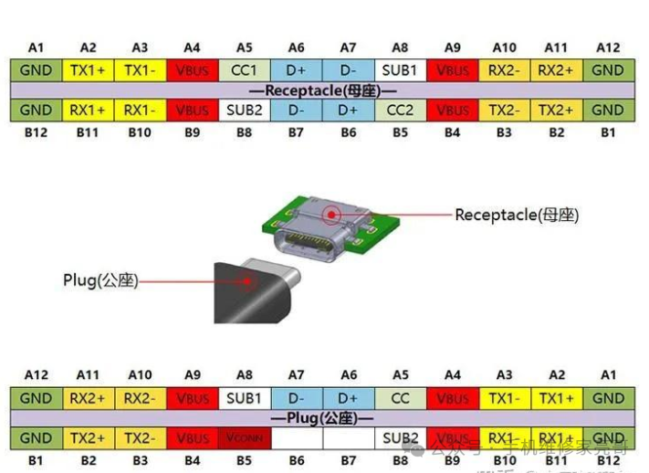
- Both sides of the interface have CC1 and CC2 pins, and the CC wires inside the cable will connect to the CC pins on both sides simultaneously, so regardless of how it is plugged in, one set of CC pins can complete the negotiation, eliminating the need to distinguish direction.
Could issues with wireless charging/fast charging be related to the CC pins?
- If a device cannot recognize fast charging or wireless charging, it may be due to poor contact with the CC pins or damaged resistors (for example, the master device’s Rp resistor burned out, or the slave device’s Rd resistor is open);
- During repairs, measure the voltage on the CC pins: when the master device is not connected, the CC pin voltage is close to VBUS (5V), and after connecting the slave device, the voltage will drop to around 0.3-1V (normal range); if there is no voltage change, it may indicate a CC link failure.
Can the master-slave roles be manually switched?
- Some devices support this (for example, a phone enabling “reverse charging” will force it to act as the master device supplying power; a computer set to “charging-only mode” will act as the slave device receiving power), essentially controlling the resistor configuration of the CC pins through software to change the negotiation results.
5. Conclusion
The essence of Type-C to Type-C connection is:determining “who supplies power, who receives power” and “who is the host, who is the slave” through the resistor negotiation of the CC pins, and then transmitting power, data, and video through the corresponding pins, achieving “multiple uses with one cable”.
When encountering Type-C connection issues during repairs, prioritize checking the CC pins (contact, resistors, voltage) and whether the cable is fully functional, as most faults are related to these two key points.
In this cold season,
it becomes warm
because of your attention.