
Industrial Control Classroom【www.gkket.com】Essential Website for Engineers
Add WeChat:gkket123 Join 500-person WeChat group
Electrical Automation – Free Materials Worth Over Ten Thousand Yuan
Click to Download for Free
(DownLoad)
When it comes to Siemens communication, we must mention PROFIBUS. Do you know what it is? How to use it?
This article is about 3000 words long and can be read in 5 minutes. After reading, you will have an intuitive understanding of PROFIBUS. PROFIBUS supports master-slave mode and multi-master multi-slave mode. In the multi-master mode, control over the bus is determined by token passing between masters. The master that obtains control can send and receive information from slaves, achieving point-to-point communication.
1. Composition of PROFIBUS
The PROFIBUS protocol includes three main parts: PROFIBUS-DP (Distributed Peripheral), PROFIBUS-PA (Process Automation), and PROFIBUS-FMS (Fieldbus Message Specification).
1.1 PROFIBUS-DP (Distributed Peripheral)
PROFIBUS-DP is a high-speed, low-cost data transmission protocol used for communication between unit-level control devices and distributed I/O (such as ET 200) in automation systems. Communication between masters is token-based, while communication between masters and slaves is based on master-slave polling, as well as a combination of these two methods. A network can have several passive nodes (slaves), while it has only one active token (master). Such a network is a pure master-slave system. Figure 1 shows a typical master-slave PROFIBUS-DP bus, with one station as the master and the others as slaves.
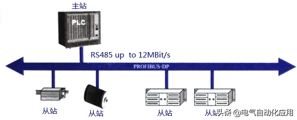
Figure 1 Typical Master-Slave PROFIBUS-DP Bus
1.2 PROFIBUS-PA (Process Automation)
PROFIBUS-PA is used for low-speed data transmission between field sensors and actuators in process automation, utilizing the extended PROFIBUS-DP protocol. The transmission technology complies with the IEC 1158-2 standard, suitable for communication between sensors and actuators in explosive environments and central control systems. It uses shielded twisted pair cables powered by the bus. A typical PROFIBUS-PA system configuration is shown in Figure 2.
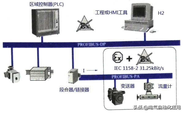
Figure 2 Typical PROFIBUS-PA System Configuration
1.3 PROFIBUS-FMS (Fieldbus Message Specification)
PROFIBUS-FMS can be used for workshop-level monitoring networks. FMS provides a large number of communication services for both cyclic and acyclic communication services at medium transmission speeds. For FMS, the primary focus is on system functionality rather than system response time. Figure 3 shows a typical PROFIBUS-FMS system composed of various intelligent automation units, such as PC, PLC, HMI, etc.
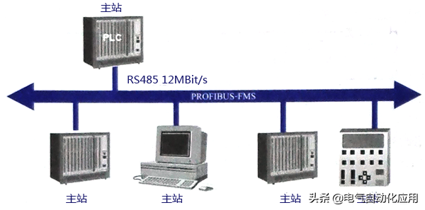
Figure 3 Typical PROFIBUS-FMS System
2. Structure of PROFIBUS Protocol
The structure of the PROFIBUS protocol is based on the ISO/OSI reference model, as shown in Figure 4. The first layer is the physical layer, defining the physical transmission characteristics; the second layer is the data link layer; layers three to six are not used by PROFIBUS; the seventh layer is the application layer, defining the functionality of the application.
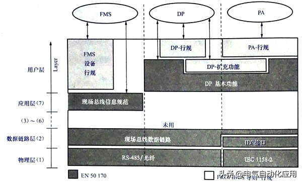
Figure 4 Typical PROFIBUS-FMS System
PROFIBUS-DP is an efficient and fast communication protocol that utilizes the first and second layers and user interface, while layers three to seven are unused. This simplified structure ensures fast and efficient data transmission for DP.
3. Transmission Technology
PROFIBUS bus uses a bus topology structure with terminals at both ends, as shown in Figure 5.
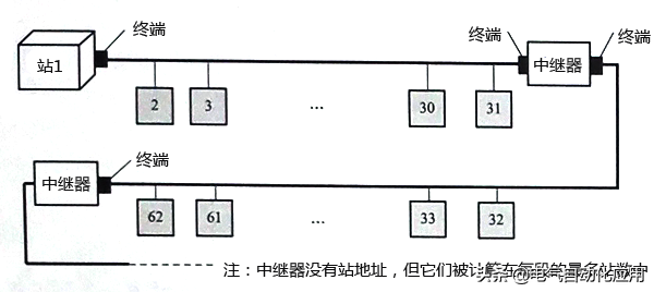
Figure 5 Bus Topology Structure with Terminals at Both Ends
PROFIBUS employs three transmission technologies: PROFIBUS DP and PROFIBUS FMS use the same transmission technology, which can utilize RS485 shielded twisted pair cables or fiber optic transmission; PROFIBUS PA uses IEC 1158-2 transmission technology; DP and FMS use the same transmission technology and unified bus access protocol, allowing them to run simultaneously on the same cable; DP/FMS complies with the EIA RS-485 standard (also known as H2), using shielded or unshielded twisted pair cables, with transmission speeds ranging from 9.6 kbit/s to 12 Mbit/s. A bus segment can have a maximum of 32 stations, and with repeaters, up to 127 stations. The transmission distance for DP/FMS is related to the transmission rate; at 3-12 Mbit/s, the maximum distance is 100m, while at 9.6-93.75 kbit/s, it is 1200m. Additionally, to adapt to environments with high electromagnetic interference or for long-distance high-speed transmission, PROFIBUS can employ fiber optic transmission technology.
4. PROFIBUS Bus Connector
The PROFIBUS bus connector is used to connect PROFIBUS stations to cables for signal transmission, equipped with built-in terminal resistors, as shown in Figure 6.
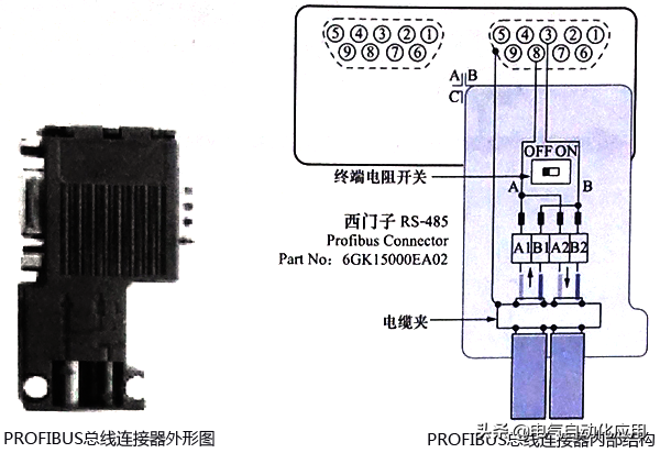
Figure 6 PROFIBUS Bus Connector
5. Correct Wiring for PROFIBUS-DP Line
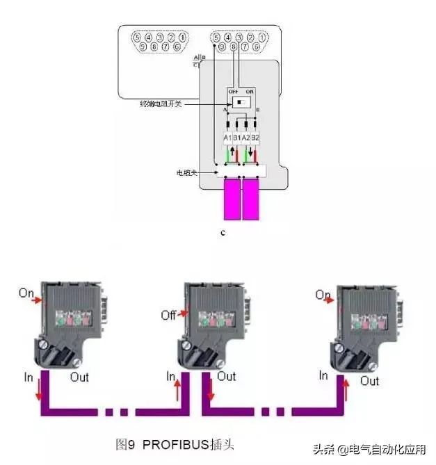
The correct wiring is shown in the figure below, which is self-explanatory. The PROFIBUS cable is simple, with only two wires inside, one red and one green, and an outer shielding layer. When wiring, ensure that the shielding layer is connected properly and does not touch the inner wires. Distinguish between the incoming and outgoing wires; if it is a chain, it means one main bus goes down, continuously connecting the sub-stations, which is a common method. At the two ends of the bus, the wires must connect to the incoming hole, not the outgoing one. The switches at both ends must be set to ON state, which means only the incoming connection is active while the outgoing connection is disconnected. The remaining intermediate connectors should be set to OFF, where both the incoming and outgoing connections are active (a mnemonic: ON indicates connecting the terminal resistor, so the end connectors are set to ON; OFF indicates disconnecting the terminal resistor, so the intermediate connectors are set to OFF).
6. Step-by-Step Guide on How to Connect and Purchase
Whether forming an MPI or PROFIBUS-DP network, the main components used are the same:
For specific cable and connector order numbers, please refer to: Common Accessory Order Numbers
A. Cables and Strippers. Use FC technology without stripping out exposed copper wires.

Figure 1. PROFIBUS cable with one end stripped using a quick stripper (FCS, order number 6GK1905-6AA00).
B. Open the PROFIBUS network connector. First, release the cable tension release block, then lift the core wire lock.
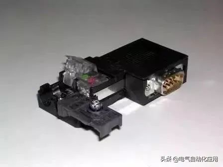
Figure 2. Opened PROFIBUS Connector
C. Remove the protective layer from the PROFIBUS cable core wire, insert the core wire into the core wire lock according to the corresponding color marking, and then press the lock block down firmly to ensure contact with the internal conductors. Ensure that the stripped shielding layer of the cable makes contact with the shielding connection clamp.
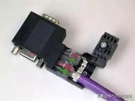
Figure 3. Inserting Cable
Due to the high communication frequency, the communication cables are grounded at both ends. The shielding layer at both ends must be connected.
D. Reset the cable clamp, tighten the screws, and eliminate external tension on the internal connections.
The network connectors are mainly divided into two types: with and without programming ports. Connectors without programming ports are used for general networking, while those with programming ports can still provide a programming connection port for programming or connecting HMIs while networking.
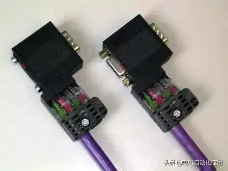
Figure 4. Left: Network connector without programming port (order number: 6ES7 972-0BA52-0XA0), Right: With programming port
Connect the PROFIBUS cable to the network plug to form a bus-type network structure.
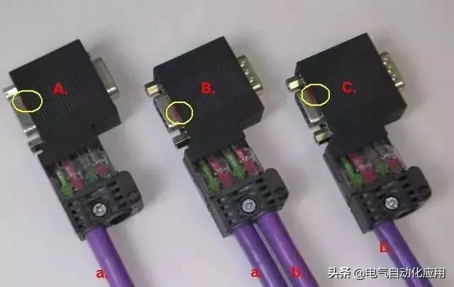
Figure 5. Bus-type Network Connection
In the above figure, network connectors A, B, and C are respectively plugged into the communication ports of three communication stations; cable a connects plugs A and B, while cable b connects plugs B and C. The linear structure can be expanded accordingly.
Note the settings of the “terminal resistor” switch within the circle. The terminal resistor switch on the network terminal plug must be set to “ON”; the terminal resistor switch on the intermediate station plugs should be set to “OFF”.
Precautions:
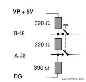
Devices with terminal resistors set to ON cannot be powered off. As shown in Figure 5, besides the 220-ohm terminal resistor, the PROFIBUS plug also has two 390-ohm bias resistors, which must be connected to the power supply.
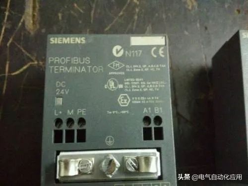
If terminal devices need to be powered off frequently for maintenance, or if terminal devices only have terminal blocks but no 9-pin D-type sockets, an active terminal module should be used as the terminal for the PROFIBUS bus (6ES7 972-0DA00-0AA0).
If the PROFIBUS cable is not long enough and needs to connect two cables, do not simply twist the two copper cores together, as this will damage the cable’s characteristic impedance and may lead to communication issues. It is best to use the connector shown in Figure 7 to connect the two cables.
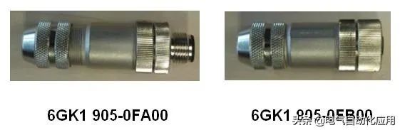
PROFIBUS Connection Joint
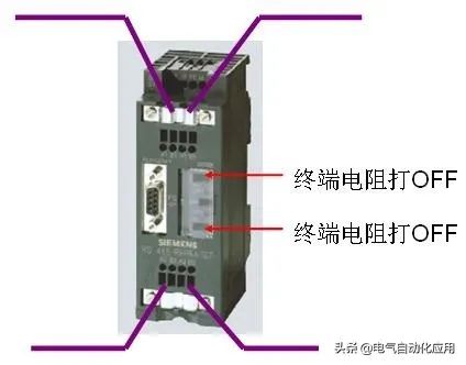
3. Usage of Terminal Resistors on RS485 Repeaters
The maximum length of the PROFIBUS communication cable depends on the baud rate of the communication. If the cable exceeds the maximum communication length, RS485 repeaters need to be used to extend the communication distance.
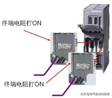
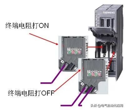
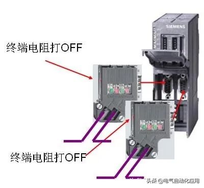
Repeaters have terminal blocks, and PROFIBUS cables can be directly connected to these terminals. Additionally, repeaters are equipped with terminal resistors, and their usage is the same as that of cable plugs.
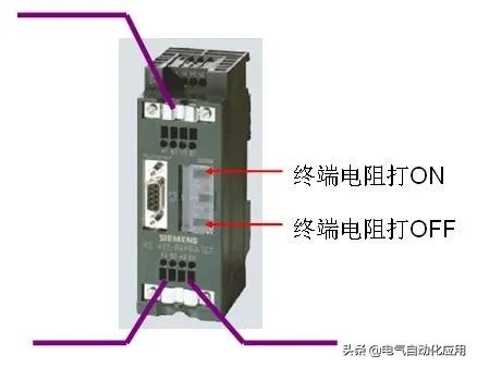
1. Network segment has only incoming line; 2. Network segment has both incoming and outgoing lines.
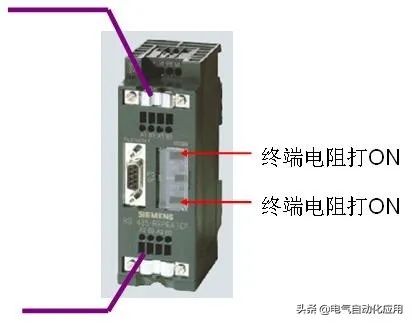
1. Network segment has only incoming line; 2. Network segment has only incoming line.
1. Network segment has both incoming and outgoing lines; 2. Network segment has both incoming and outgoing lines.
4. Usage of Terminal Resistors on OLM Plugs
If the communication distance of field devices is relatively long, or if there is severe electromagnetic interference in the field, OLM can be used to convert electrical signals into optical signals, using optical cables for signal transmission. OLM has RS485 electrical interfaces that require PROFIBUS plugs for cable connections. The wiring is the same whether connecting to a master or a slave.
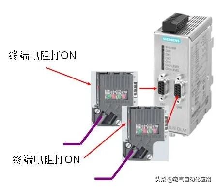
1. Network segment has only incoming line; 2. Network segment has only incoming line.
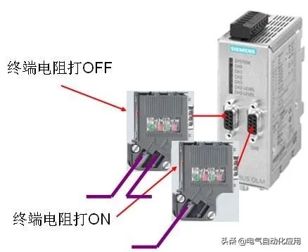
1. Network segment has both incoming and outgoing lines; 2. Network segment has only incoming line.
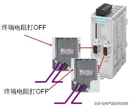
1. Network segment has both incoming and outgoing lines; 2. Network segment has both incoming and outgoing lines.
For OLMs with only one RS485 interface, it can be considered as having only one network segment, and the wiring is the same.
5. Usage of Terminal Resistors on DP/DP Couplers
Two DP masters can use DP/DP couplers to transmit data. The DP/DP coupler has two RS485 interfaces, and the connection method is the same as that of OLM.
1. Network segment has only incoming line; 2. Network segment has only incoming line.
1. Network segment has only incoming line; 2. Network segment has both incoming and outgoing lines.
1. Network segment has both incoming and outgoing lines; 2. Network segment has both incoming and outgoing lines.
In fact, many times, PROFIBUS-DP gives people a sense of insecurity, mainly because its operation coefficient is relatively high. However, as long as all work is done very well, it can also be very stable.
Although more and more people prefer to use PROFINET now, there are still many old devices using PROFIBUS-DP, so mastering it is also very necessary!
Important Notice
If you want to join the Electrical Automation Technology Exchange Group, please add the class leader as a friend and note: region – industry – name/nickname to get the qualification to join the group.

Electrical Automation<br/>Professional Focus Sharing<br/><br/>Share to Moments and share with friends<br/>——————————————————————<br/>▣ Source: Network - Baidu Wenku, infringement deletion!<br/>▣ Statement: We respect originality. The copyright of text, images, and video materials belongs to the original author. Some articles could not be contacted with the original author for various reasons during the push. If copyright issues arise, please contact us for deletion (contact 17621634088 - WeChat same number), we only share for non-commercial purposes.
They are all following, what are you waiting for?