SD
The SD card (secure digital card) is a low-cost, non-volatile storage card format developed by the SD Card Association (compared to RAM, data on an SD card is not lost when power is off);
With the rapid development of electronic technology in this century, the demand for such medium-sized, energy-efficient, and space-saving storage devices has been growing quickly;
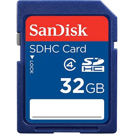
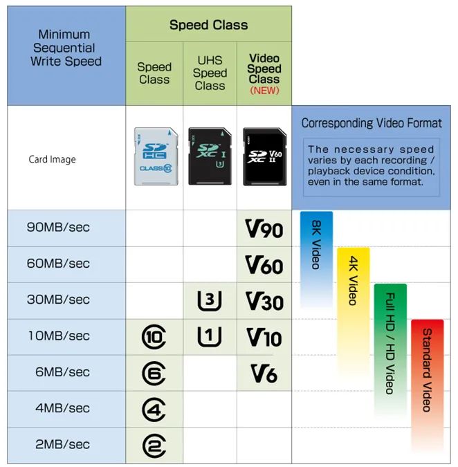
The SD card has speed classes of SDHC, which range from; Class 2 (operating at 2 MB/s);Class 4 (operating at 4 MB/s);Class 6 (operating at a maximum speed of 6 MB/s);Class 10 (operating at the highest speed of 10 MB/s);
SDXC cards operate atUltra High Speed and can reach speeds of up to 30 MB/s; they also have avideo speed class with data transfer rates of up to 90 MB/s.
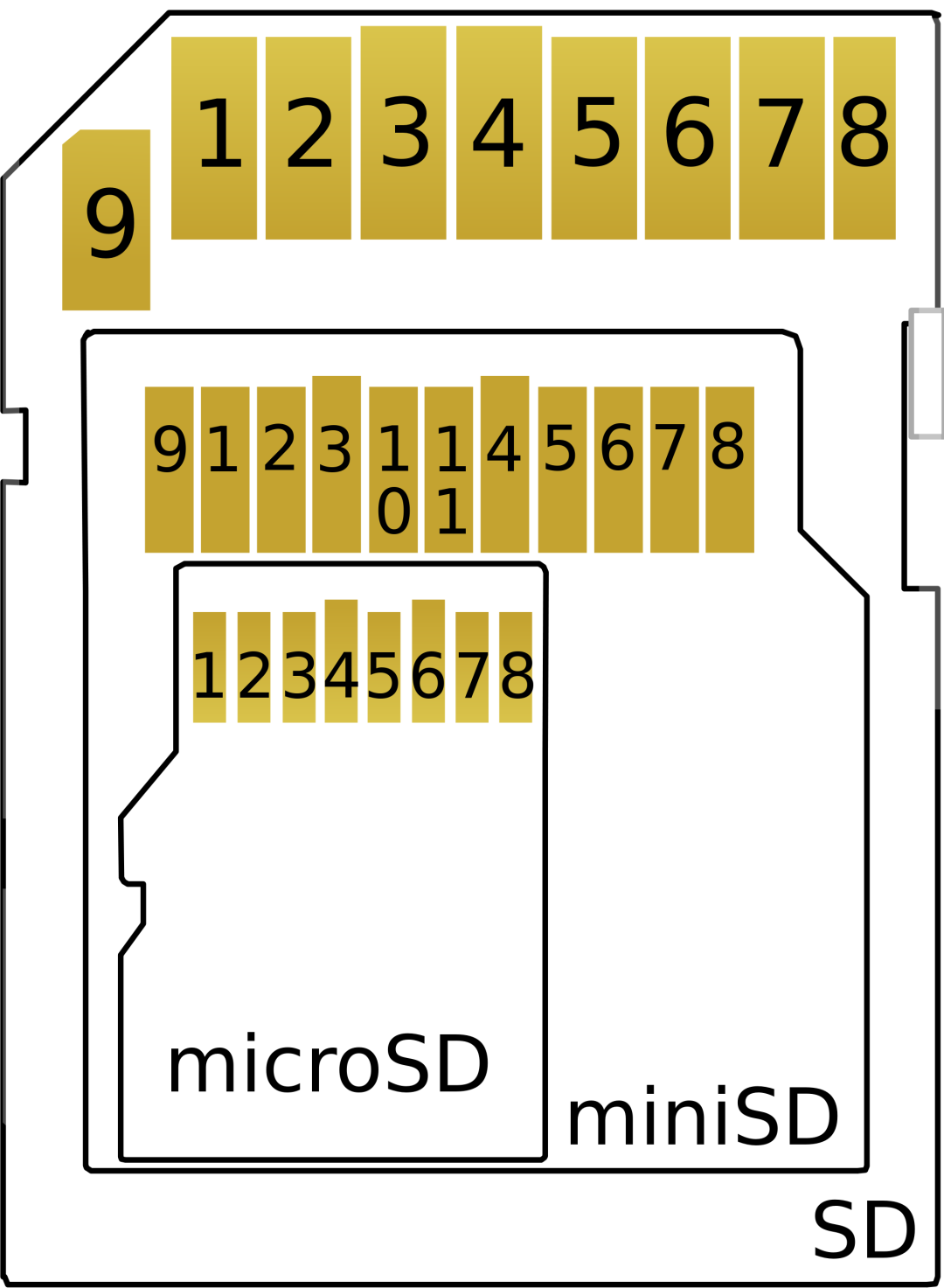
SD cards also come in different sizes or form factors, including standard SD cards, mini SD cards, and micro SD cards;
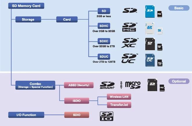
SD cards can be standard SD cards with a storage capacity of up to 4 GB, high-capacity cards (SDHC) with up to 64 GB, and extended capacity cards (SDXC) that can reach TB levels.
Interface
SD cards can operate in SD bus mode or SPI bus mode, and usually can be driven using the SDIO bus or SPI;
Here, we mainly take micro SD as an example to briefly introduce the SDIO mode and SPI mode;
microSD Pin Output, SD Mode
| Pin | Pin Name | Signal Function |
|---|---|---|
| 1 | DAT2 | Data Bit 2 |
| 2 | CD / DAT3 | Card Detect / Data Bit 3 |
| 3 | CMD | Command Line |
| 4 | Vdd | Power Voltage 2.7v / 3.6v |
| 5 | Clk | Clock |
| 6 | VS | Ground |
| 7 | DAT0 | Data Bit 0 |
| 8 | DAT1 | Data Bit 1 |
microSD Pin Output, SPI Mode
| Pin | Pin Name | Signal Function |
|---|---|---|
| 1 | NC | No Connection |
| 2 | /CS | Chip Select |
| 3 | DI | Master Out / Slave In (MOSI) |
| 4 | Vdd | Power Voltage 2.7v / 3.6v |
| 5 | Clk | Clock |
| 6 | Vss | Ground |
| 7 | DO | Master In / Slave Out (MISO) |
| 8 | RSV | Reserved |
The pinout of micro SD is shown in the following figure;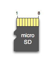
Protocol
In the SD protocol, since the command data line and data lines are separate, we need to focus on the transmission format of commands and data;
Command Transmission
Commands are transmitted in the form of 48-bit packets through the bidirectional CMD pin.
These command packets include command index, variables, and CRC bits. The command is always sent by the host and ultimately received by the SD card.
The returned response packet is also 48 bits.
The overall command format is shown in the figure below;
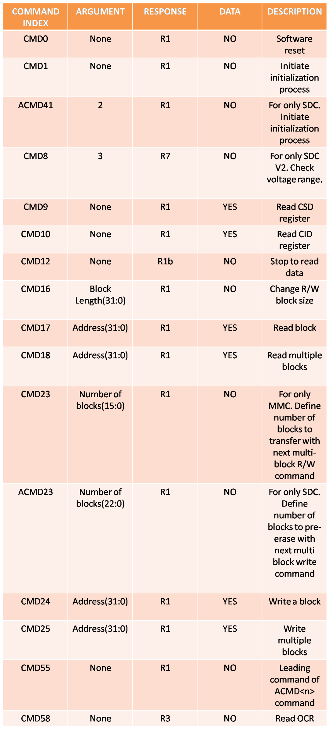
48-bit Command Format
Each command has a constant length of 6 bytes. The first byte is the command number plus 64. For example: For CMD0: command number 0 + 64 = 64 = 0x40 (hexadecimal).
For CMD1: hexadecimal command number 1 + 64 = 65 = 0x41.
Followed by a set of four bytes known as parameters.
These parameters typically contain the address of the data or the length of the block.
The last byte is the CRC (Cyclic Redundancy Check) byte.
If the CRC function is not enabled, most commands in SPI mode do not require a check byte.
For certain commands, such as CMD0, the CRC is 0x95, while in most cases, 0xFF is sent.
Enabling CRC requires you to send the correct check byte from the microcontroller. Therefore, ensure that the CRC function is enabled or disabled.
The format for sending commands is shown below;
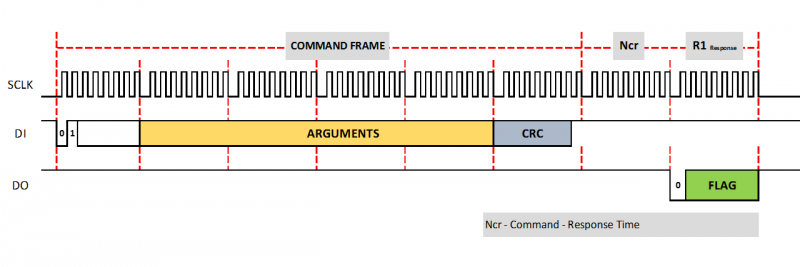
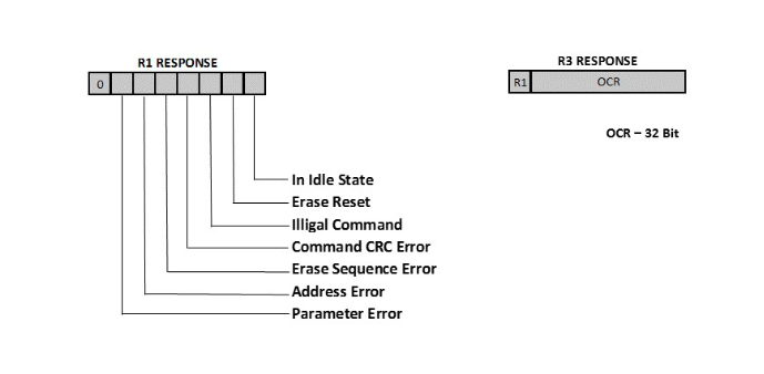
R1 response 0x01 indicates that the command sent prior to the response has caused the card to enter idle state. A response byte of 0x00 indicates that the command has been accepted, and the SD card will wait for subsequent events. If any other bits in the R1 response are set, it is an error result, and the error will be reduced to the factors mentioned in each R1 response bit in the figure.
Different types of responses and their meanings are shown below;
Data Transmission
During data transmission, the basic unit of transmission is called a block, typically 512 bytes, and is transmitted through all four data pins. Similarly, after each block transmission, a 16-bit CRC data will be sent.
Note that the SD card operates in states. Each state has a different command set, and the host can change the state through controls.
Command and data signals are synchronized by clock signals. Initially, the host communicates with the card using a 400KHz clock, but eventually, it will increase the clock speed to maximize efficiency during transmission.
Because before initialization, the host does not know whether it is an SD card or an MMC card.
By default, the MMC card operates in open-drain mode (100-400KHz) during initialization, while the SD card operates in push-pull mode (0-25Mhz).
Therefore, initially, the host uses 400KHz to maintain compatibility with both open-drain and push-pull modes.
Hardware Design
SDIO
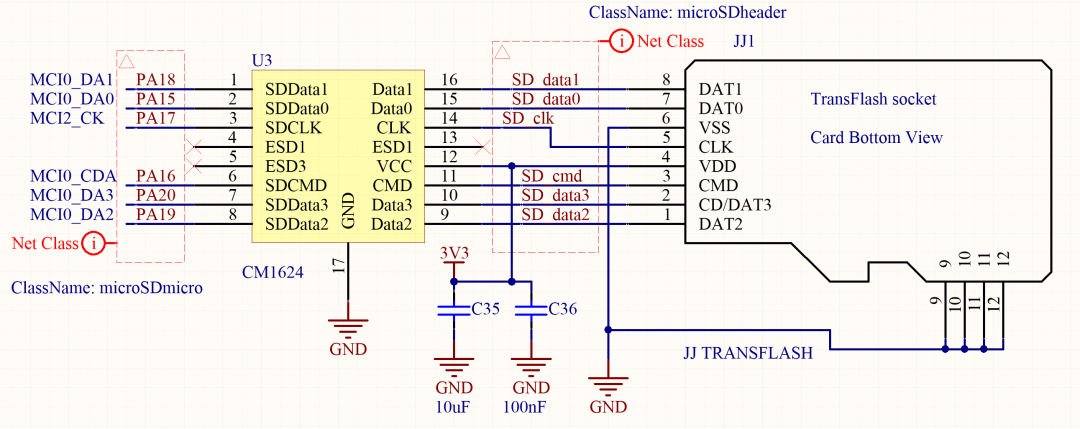
This is an example of a 4 Bit connection from SD/MMC peripherals to the SD card slot.
Using Data[3..0], CLK, and CMD signals.
The SD card slot is exposed to the external environment. Even when not connected to any other device, it may be affected by static electric charges accumulated in the human body, which release into the shield when touched.
To comply with EMC standards, some routine precautions must be taken to filter and avoid conducted radiation. Additionally, the SD card specification also stipulates pull-up resistors and series impedance matching resistors.
Fortunately, as SD has become so widespread in mobile devices, integrated solutions have emerged that can achieve all these functions at once.
CM1624 is a combination of EMI filter and line termination device with integrated TVS diodes, used for T-Flash / MicroSD interfaces.
SPI
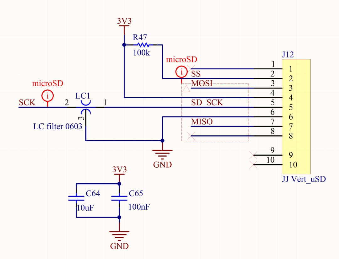
Below is an example of an SD card used in SPI mode, connected according to the SD Association specifications with MISO, MOSI, CLK, and CS signals.
We only need to apply a filter on the clock line to improve EMC in very harsh environments.
In SDIO mode or SPI mode, tracks transmit data and clock signals at high data rates.
To avoid signal spikes, signal propagation time must be considered to ensure that all data is stable at the interface before clock-triggered read or write operations.
The path lengths of all data signals must match within a few tenths of a millimeter, and the clock length should be about 1 millimeter.
To avoid crosstalk, these traces must maintain a good ground plane around and below them and should also connect layers with a sufficient number of vias.
Conclusion
This article briefly introduced the classification and common properties of SD cards, and also provided a brief introduction to the SD card protocol, giving example circuits for SPI bus and SDIO bus in hardware design. Due to space limitations, the software part has not been expanded upon;
Reference: “Secure Digital Input/Output (SDIO) Card Specification”
 ENDClick on the top“Breadboard Community”, select“Top/Star Public Account”
Electronic technology insights delivered promptly

-
What circuit implements the button function of a TV? Classic ADC button circuit
-
This small electric mosquito swatter surprisingly has so many basic circuits, how many can you understand?
-
The principle of the 220V lamp string circuit is actually like this!
-
Don’t underestimate the humble resistor; there’s a lot to learn!
-
Simple explanation of MOSFETs
-
Illustrated automotive-grade chips