0x01. Camera SD Card Flashing Experience
Recently, I researched the SD card flashing function of a camera I have. This camera only supports SD cards formatted as FAT32, so the SD card needs to be formatted to FAT32 first. Additionally, Microsoft limits the maximum capacity of FAT32 to 32GB, so only SD cards not exceeding 32GB can be used for flashing.
Here, a 32GB SD card is used for flashing.
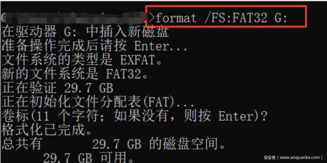
The command to format the SD card in Windows 10, where X is the drive letter of the SD card.
format /FS:FAT32 X:Once ready, place the firmware file FIRMWARE.bin in the root directory of the SD card and press and hold the reset button to flash the firmware.
However, I later found that it was unsuccessful; after flashing, the camera became a brick and failed to start normally. At this point, the firmware flashed was still the normal firmware, and no modifications had been made. It indeed started off poorly, and I was unsure which step went wrong.
0x02. Rescue Operation for the Brick
After the camera failed to start normally post-flashing, I considered connecting via serial to see where the issue lay.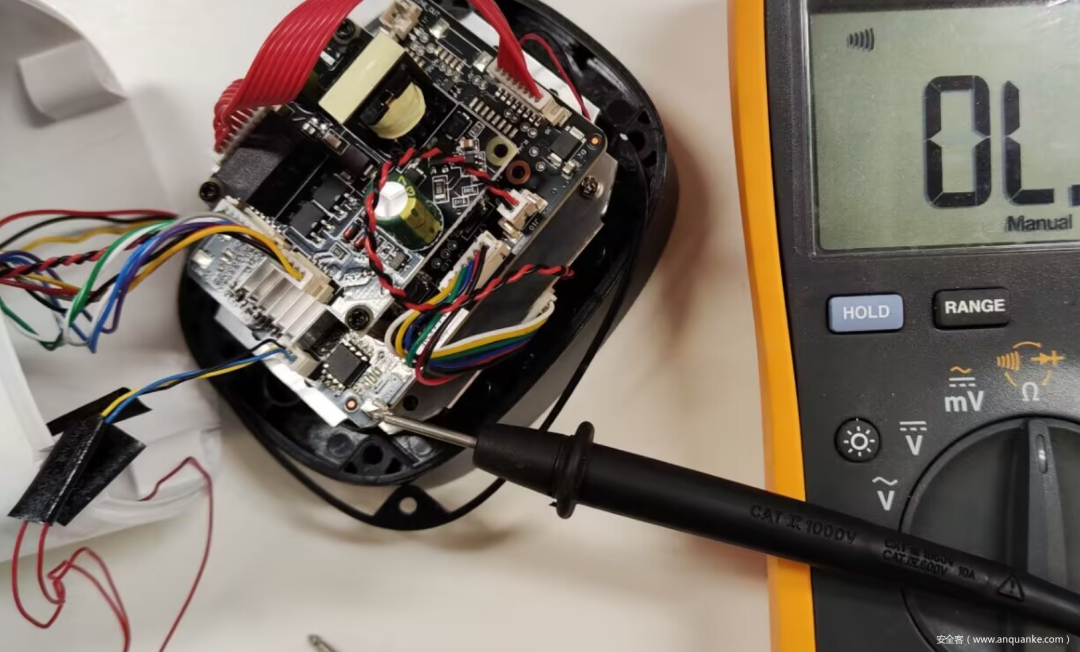 After connecting the serial, I powered on the device and observed the following serial log:
T
IPL xxx
D-15
HW Reset
SPI 54M
IPL_CUST xxxx
MXP found at 0x0000f000
offset:00010000
XZ decomp_size=0x0004a19c
U-Boot 2015.01
WARNING: Caches not enabled
MMC:   MStar SD/MMC: 0
SF: Detected nor0 with total size 8 MiB
gpio debug MHal_GPIO_Pad_Set:603
gpio debug MHal_GPIO_Pad_Set:603
In:    serial
Out:   serial
Err:   serial
Net:   MAC Address E0:EF:02:88:AD:26
Auto-Negotiation...
Link Status Speed:100 Full-duplex:1
sstar_emac
gpio debug MHal_GPIO_Pad_Set:603
ddrsize 64
mtd_num 5, flash_size 0x00800000(8M)
To run up...
Using sstar_emac device
TFTP from server 192.168.1.99;
 our IP address is 192.168.1.10
Filename 'update.bin'.
Load address: 0x21000000
Loading: T T T T T T T T T T
Retry count exceeded; starting again
Using sstar_emac device
TFTP from server 192.168.1.99;
our IP address is 192.168.1.10
Filename 'update.bin'.
Load address: 0x21000000
Loading: T T T T T T T T T T
From the log information, it can be seen that the camera’s IP address is 192.168.1.10, and the TFTP server address is 192.168.1.99. The device attempts to load the firmware named update.bin from the TFTP server but fails.This indicates that the previous SD card flash was unsuccessful, and now the device is powered on and actively attempting to use the TFTP function in U-Boot to load firmware from 192.168.1.99, but the server at 192.168.1.99 does not exist, so the camera is stuck here and cannot start normally.I attempted to use TFTP to flash the camera. Since the device cannot successfully interrupt U-Boot to enter the shell during startup, we cannot directly modify the default TFTP server IP and perform other operations through the U-Boot shell. Instead, I had to set up a TFTP server on the PC, modify the IP to 192.168.1.99, and name the firmware to be flashed as update.bin and place it in the TFTP server directory.Once the TFTP server was ready, I powered on the device again and observed that it successfully downloaded the firmware from the server at 192.168.1.99 and wrote it to flash, successfully rescuing the brick.Afterwards, I followed the SD card flashing process again to attempt to flash the normal firmware, and finally, there was no further occurrence of the brick situation.
T
IPL xxx
D-15
HW Reset
SPI 54M
IPL_CUST xxxx
U-Boot 2015.01
WARNING: Caches not enabled
MMC:   MStar SD/MMC: 0
SF: Detected nor0 with total size 8 MiB
gpio debug MHal_GPIO_Pad_Set:603
In:    serial
Out:   serial
Err:   serial
Auto-Negotiation...
sstar_emac
SF: Detected nor0 with total size 8 MiB
Erasing SPI flash..._spi_flash_erase:
 addr 0x30000,
len 0x10000 100%(cost 248 ms)
Writing to
SPI flash..._spi_flash_write
to 0x30000,
len 0x10000 from
 0x23b01870 100%(cost 169 ms)
done
ddrsize 64
mtd_num 5,
flash_size 0x00800000(8M)
To run up...
Using sstar_emac device
TFTP from server 192.168.1.99;
our IP address is 192.168.1.10
Filename 'update.bin'.
Load address: 0x21000000
Loading:


T #################################################
###################################################
#######################################################
#######################################################
#######################################################
#######################################################
#######################################################
#######################################################
#######################################################
##############


         237.3 KiB/s
doneBytes transferred =
7114336 (6c8e60 hex)
head_crc32 9ba634e1
 crc32 9ba634e1
MXIC REMS: 0xC2,0x16
SF: Detected nor0 with total size 8 MiB
...
...
SF:
1507328 bytes @ 0x40000
Written: OK
head_crc32 4d5121d7 crc32 4d5121d7
...
...
Erasing SPI flash..._spi_flash_erase:
 addr 0x30000,
 len 0x10000 100%(cost 255 ms)
Writing to
SPI flash..._spi_flash_write
to 0x30000,
len 0x10000
from 0x23b018d0 100%(cost 175 ms)
done
resetting ...
##  Booting kernel
 from Legacy Image at 21000000 ...
Image Name:MVX4##I6B0xxxxxxxx
Image Type:
ARM Linux Kernel
 Image (lzma compressed)
   Data Size:1494344 Bytes = 1.4 MiB
   Load Address: 20008000
   Entry Point:  20008000
   Verifying Checksum ... OK
   Uncompressing Kernel Image ...
[XZ] !!!reserved 0x21000000
 length=0x 1000000 for xz!!
   XZ: uncompressed size=0x2e2000,
ret=7
OK

Starting kernel ...
0x03. Analyzing SD Card Firmware Checksum
The normal SD card flashing process is generally as follows: first, power off, insert the SD card containing the firmware into the camera, press and hold the reset button, and then power on. At this time, the camera will load the SD card firmware for flashing. The purpose of holding the reset button is to force the camera into IPL mode (Initial Program Loader), also known as recovery mode.This mode allows the device to load new firmware stored on the SD card and update the existing firmware.In IPL mode, the device will not automatically run the existing firmware but will wait for new firmware to be loaded from the SD card for flashing.Thus, holding the reset button ensures that the device can correctly enter IPL mode to complete the firmware update. In this log, it can be seen that the IPL (Initial Program Loader) has been successfully loaded and passed the check.The IPL_CUST firmware’s role is to start U-Boot, which then loads and runs the device’s operating system. During this process, U-Boot reads the firmware from the SD card, loads it into the camera’s memory, and starts the Linux kernel.Therefore, the program to load the SD card firmware is in U-Boot. From the logs above, it can be seen that U-Boot performs a CRC check on the firmware when starting it. Thus, after modifying the firmware, it is necessary to consider the CRC check to ensure successful flashing.Indeed, strings related to the CRC check can be found in the U-Boot firmware from the logs above. Analyzing the CRC check logic in U-Boot, I reverse-engineered the relevant fields that need to be calculated after modifying the firmware.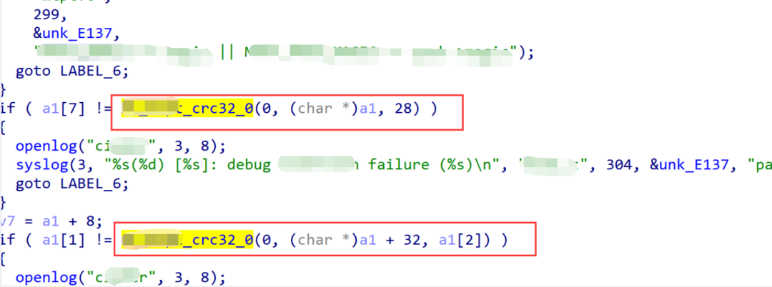
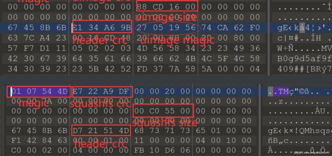
0x04. Custom File System
Knowing the structure of the firmware, the next step is to implant our own program into the firmware’s file system. After modifying the firmware, calculate and adjust the corresponding size and CRC field values, then flash it back into the device using the SD card.Using Buildroot, compile a BusyBox that includes features like telnet and ftp, and transplant the newly compiled BusyBox into the camera’s original file system.Download Buildroot and select the compilation configuration.
make menuconfig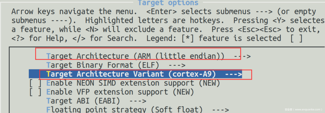
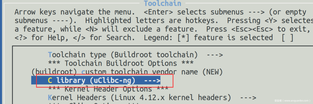 Next, compile BusyBox and include telnetd in the build.
make busybox-menuconfig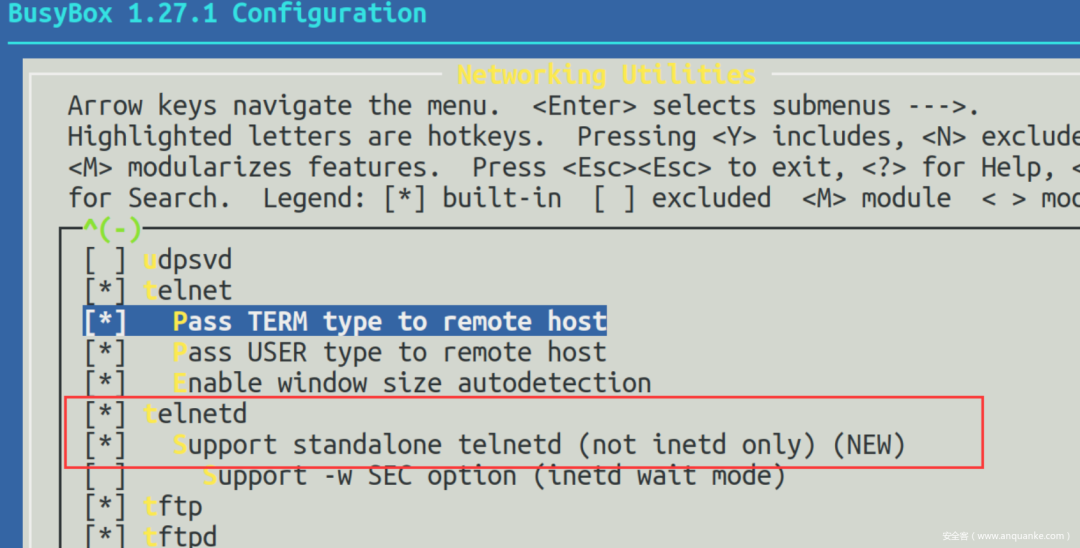 After completing the above settings, execute
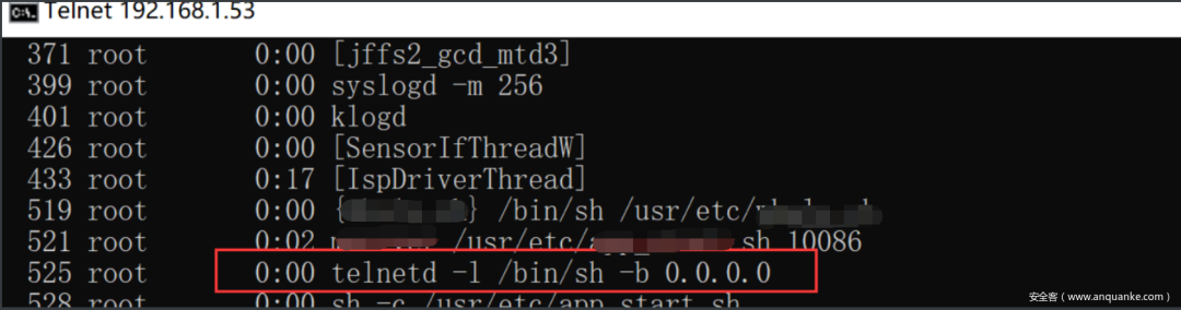
<span>make</span> to compile. After compilation, an output folder will be generated in the current directory. The generated telnetd is linked to BusyBox, so here, we can directly transplant the generated BusyBox into the camera’s file system. Copy the compiled BusyBox to the firmware file system’s /bin directory and rename it to busybox_hack.When unpacking the firmware, remember to use root permissions since the camera runs as the root user. When copying busybox_hack into the camera’s file system, also ensure to modify the file’s ownership and group to match other files.Add busybox_hack to the startup items in /etc_default/init.d/ and start telnetd, with the -l parameter linking it to /bin/sh, allowing for direct login without a password.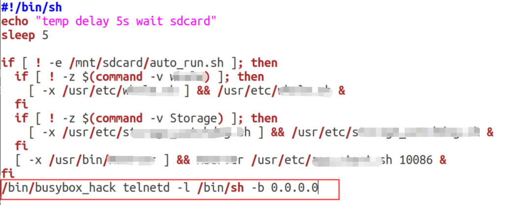 Finally, repack the file system.
sudo mksquashfs ./squashfs-root/ out.fs -comp xz -b 64K -noappendWhere <span>./squashfs-root</span> is the directory to be packed, and <span>out.fs</span> is the desired name for the repacked file. <span>-comp xz</span> tells mksquashfs to use the xz compression algorithm, and <span>-b 64K</span> tells mksquashfs to use a block size of 64K. <span>-noappend</span> tells mksquashfs not to append new files to existing ones.Overwrite out.fs at the original firmware file system location and adjust the corresponding size and CRC field values in the firmware.
dd if=out.fs of=target.bin conv=notrunc bs=1 seek=1494600if=out.fs indicates the input file is out.fs.
of=target.bin indicates the output file is target.bin.
conv=notrunc means not to truncate the output file, preserving the existing content.
bs=1 means reading and writing one byte at a time.
seek=1494600 indicates writing starts at offset 1494600 in the output file, effectively appending the input file at that offset.Finally, flash the firmware via SD card, the file system successfully boots, and telnetd starts successfully, allowing direct connection to the camera’s shell via telnet.