Understanding MODBUS Communication in One Article
We have a laser distance meter with a measurement range of 0-300mm, which outputs data via RS485 communication in actual value format. Data is collected using the FX5U Mitsubishi PLC and displayed on a Weintek HMI.
Next, let’s look at how to implement 485 communication in the FX5U.
Based on the setup steps shared in previous articles:
Confirm communication specifications → System configuration → Wiring → Communication settings → Programming
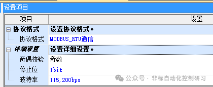
Communication specifications: The instrument in this case uses MODBUS RTU communication, with a baud rate of 115200bps, data length of 8 bits, odd parity, 1 stop bit, and a configurable station number.
System configuration: According to the communication specifications of the above instrument, we use the FX5U series PLC for data collection. You can open the PLC’s system parameter configuration:
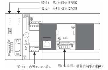
Wiring:
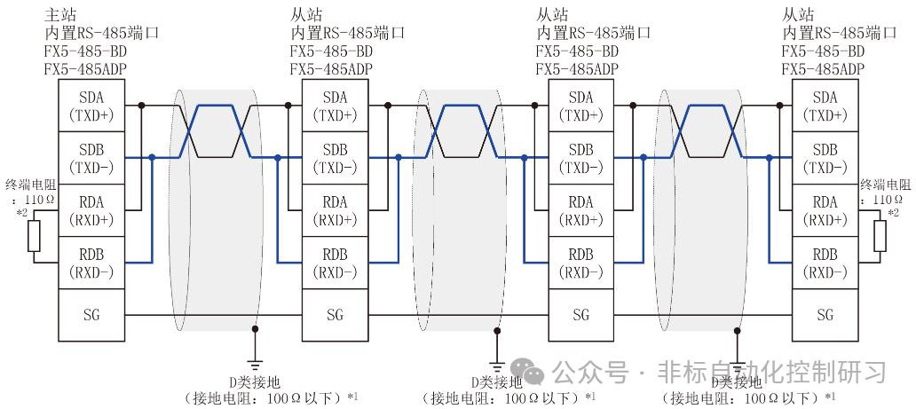
According to the previously introduced wiring method, a 2-wire system is used, directly utilizing the built-in communication port of the CPU, as shown in the figure below:
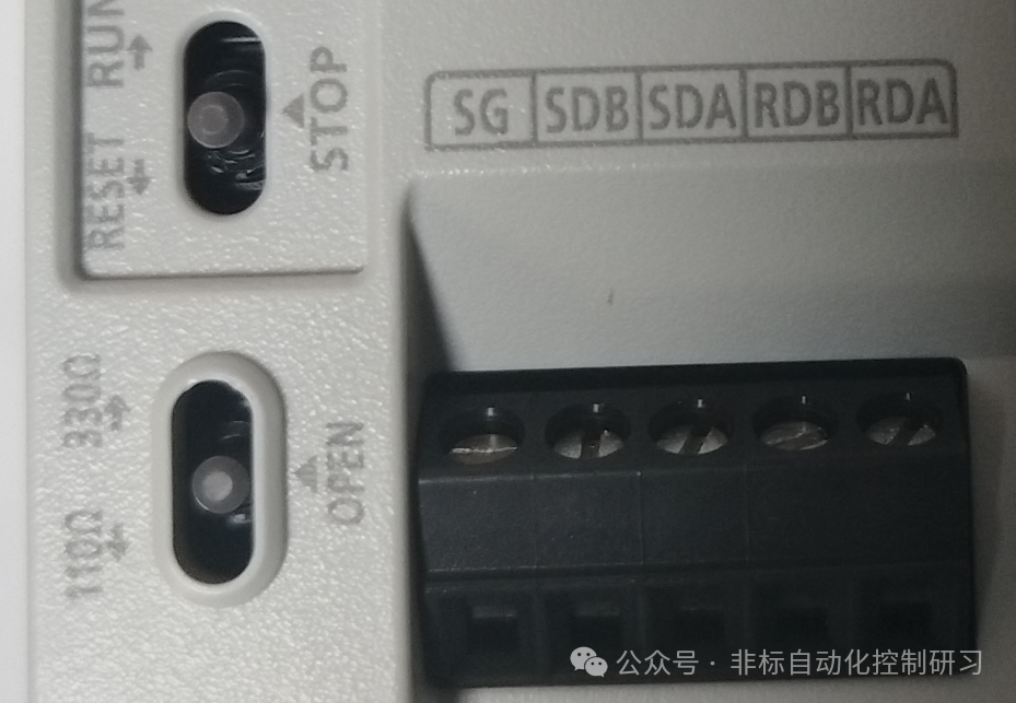
Therefore, only SDA and SDB need to be connected, while RDA and RDB should be shorted to the corresponding SDA and SDB. The terminal resistance switch should be set to ☞ 110Ω. The attached wiring schematic is as follows:
At this point, the system configuration and wiring part is basically complete.
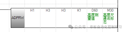
Now we can proceed to programming. In previous articles, we only briefly introduced communication instructions. Now we can provide a detailed explanation based on this case. The programming instructions are as follows:
Detailed instruction introduction:
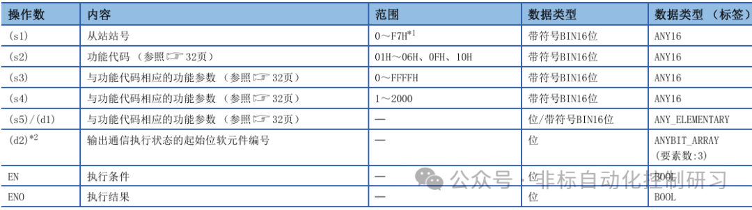
The first parameter: indicates the station number of the slave device, set to 1 here.
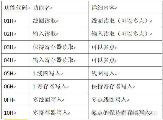
The second parameter: indicates the function code, which refers to the operation to be performed on the instrument. Here it is H3, which means to read the holding register of the instrument.
The third parameter: corresponds to the operation number of the second parameter function code, indicating the address of the holding register to be read. Here, H3 refers to the third holding register, and the specific data meaning stored in the instrument’s holding register address is defined by the manufacturer. When purchasing the instrument, the manufacturer will provide a programming manual to the user. For example, in this case, the data stored in the register address is the actual measurement data.
The fourth parameter: indicates the number of data to be accessed. In this case, H1 indicates that one piece of data is to be read from the holding register address.
The fifth parameter: indicates the starting address of the soft element where the data read from the instrument will be stored. Here, D60 is used to store the real-time data measured by the distance meter.
The sixth parameter: indicates the instruction execution flag, occupying 3 soft elements. In this case, it occupies M30/M31/M32.
Output status description:
M30: ON during instruction execution, OFF when the command is being executed, and each channel has a corresponding special relay: SM8800 (Channel 1), SM8810 (Channel 2), SM8820 (Channel 3), SM8830 (Channel 4). These four channels correspond to the four channels introduced earlier, as shown in the figure below:
M31: ON when the command ends normally, OFF when communication starts.
M32: ON when the command ends abnormally, OFF when communication starts.
With the above instructions, we can save the real-time data measured by the instrument and store it in a data register. By setting the corresponding display window on the HMI, we can complete real-time data display monitoring, such as a curve graph.
Other operations on the instrument follow the same principle, requiring a change in the corresponding function code.
Different instruments may have variations in the holding register addresses defined by the manufacturer, but otherwise, they are generally the same. The communication method must comply with the MODBUS RTU communication standard, so understanding one is equivalent to understanding them all.