
——Image source: National College Student Electronic Design Competition Training Network
Since the last time, we talked extensively about power supply aspects. It feels like we discussed something, yet it seems like we didn’t cover much. The main point is that we really can’t say much. If I just drop a link, it would be purely promotional, which is not good. So, I mainly listed some general types, and at the end of the article, I provided some personal recommendations, such as using charge pump solutions for low current requirements and some applications of LDOs and DC-DC converters. The more I write, the more contradictory it feels because electronics are inherently contradictory. Any conclusion drawn without considering the actual situation is likely to be wrong 80% of the time. So, after much thought, I believe it’s better to provide some personal insights without making any definitive conclusions.
This issue mainly involves some common parameters of ADCs and the general usage of ADCs that can be purchased.
1. Basic Parameters
1. Resolution (N)
Definition: The ability of an ADC to resolve the smallest increment of analog voltage, measured in “bits”.
Core: An N-bit ADC can quantize the signal into 2^N discrete digital levels; the higher the resolution, the more detailed the signal description.
2. Full-Scale Range
Definition: The maximum analog input voltage range that the ADC can convert (e.g., 0V~5V, FSR is 5V).
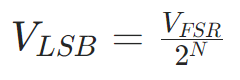
3. Least Significant Bit (LSB)
Definition: The smallest voltage change that the ADC can resolve, which is the voltage difference between adjacent digital codes.
Formula:
2. Static Parameters (DC Accuracy)
- Offset Error
Definition: The vertical offset of the actual transfer characteristic curve from the ideal curve (non-zero output when input is 0V).
Measurement: The difference between the actual input and the ideal value (0.5 LSB) when the first code value changes.
Unit: LSB or mV.
- Gain Error
Definition: The deviation of the slope of the actual transfer curve from the ideal slope (error near full scale).
Measurement: The difference between the actual input and the ideal value (FSR – 1.5 LSB) when the last code value changes, minus the offset error.
Unit: LSB or % FSR.
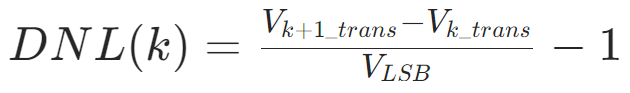
- Differential Non-Linearity (DNL)
DNL=0 LSB: Ideal state;
DNL>0 LSB: Step size is too wide;
DNL<0 LSB: Step size is too narrow;
If DNL <-1 LSB, “missing codes” will occur (some digital codes will never appear).
Definition: The difference between the actual step size of adjacent digital codes and the ideal step size (1 LSB).
Formula:
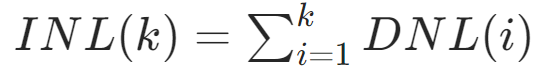
- Integral Non-Linearity (INL)
Definition: The maximum deviation of the actual conversion points from the ideal straight line, reflecting the cumulative effect of DNL.
Formula:
Importance: Directly affects signal fidelity; non-linearity can lead to harmonic distortion.
3. Dynamic Parameters (High-Frequency Performance, Analyzed via FFT)
- Signal-to-Noise Ratio (SNR)
Physical Meaning: For every additional bit of resolution, SNR increases by approximately 6dB.
Definition: The ratio of the RMS power of the signal to the power of non-harmonic noise.
Ideal Formula (dB):
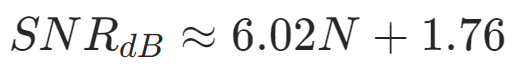
Practical Limitations: Thermal noise, clock jitter, etc., can cause the actual SNR to be lower than the theoretical value.
- Total Harmonic Distortion (THD)
Definition: The ratio of the total power of harmonic components to the power of the fundamental wave.
Formula (dBc):(This is very important! This parameter is often tested in competitions, not necessarily in ADC performance parameters, but for calculating this for a certain signal; other signal parameters also have this, just in a different form)
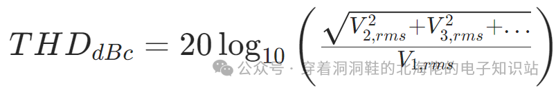
Application: A key indicator for measuring signal fidelity in audio and communication systems.
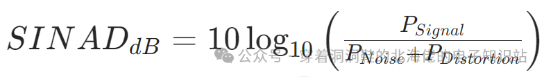
- Signal-to-Noise and Distortion Ratio (SINAD)
Definition: The ratio of signal power to the total power of noise + distortion, representing overall dynamic performance.
Formula (dB):
- Effective Number of Bits (ENOB)
Definition: The number of ideal ADC bits equivalent to the actual ADC performance (less than the physical resolution N).
Formula:
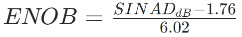
Function: To uniformly compare the dynamic performance of different ADCs.
- Spurious-Free Dynamic Range (SFDR)
Definition: The ratio of the amplitude of the fundamental wave to the maximum amplitude of spurious signals (harmonics or interference).
Unit: dBc (relative to the fundamental wave) or dBFS (relative to full scale).
Application: Determines the ability to detect weak signals in communication systems.
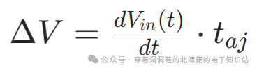
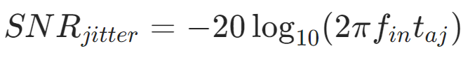
- Aperture Jitter, (t_{aj}))
Definition: The time uncertainty of the sampling clock, leading to sampling errors for high-frequency signals.
Impact: The error is proportional to the signal slew rate.
Limitations on SNR: The limitations are significant at high frequencies (e.g., 1ps jitter at 100MHz results in an SNR limit of about 68dB).
The above images are sourced from the internet; please contact the public account for deletion if there is any infringement.