

In PLCs, there are three main quantities:Switching Quantity, Analog Quantity, Pulse Quantity. Once you understand the relationship between these three, you will master PLCs proficiently.
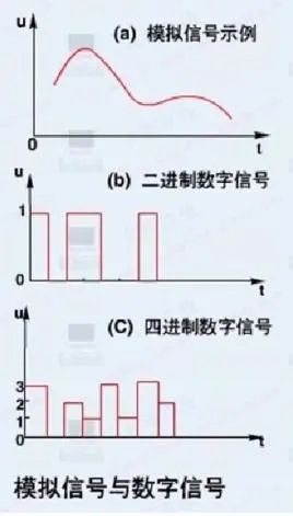
1. Switching Quantity also known as logical quantity, refers to two possible values, 0 or 1, ON or OFF (Switching quantities only have two states 0/1, including input and output quantities, reflecting the state). It is the most commonly used control, and controlling it is the advantage of PLCs, as well as the most basic application of PLCs.
The purpose of switching quantity control is to generate corresponding switching quantity outputs from the current input combinations and historical input sequences, allowing the system to operate in a specific order. Therefore, it is sometimes referred to as sequential control.
Sequential control can be divided into manual, semi-automatic, or automatic. The control principles adopted can be classified into three types: decentralized, centralized, and hybrid control.
2. Analog Quantity refers to continuously varying physical quantities (Digital quantities are discontinuous. They reflect the measured values of electrical quantities), such as voltage, current, pressure, speed, flow rate, etc.
PLCs were developed after the introduction of microprocessing technology into relay control, and they can be used conveniently and reliably for switching quantity control. Since analog quantities can be converted into digital quantities, and digital quantities are merely multi-bit switching quantities, PLCs can also reliably process and control the converted analog quantities.
Because continuous production processes often involve analog quantities, analog quantity control is sometimes referred to as process control.
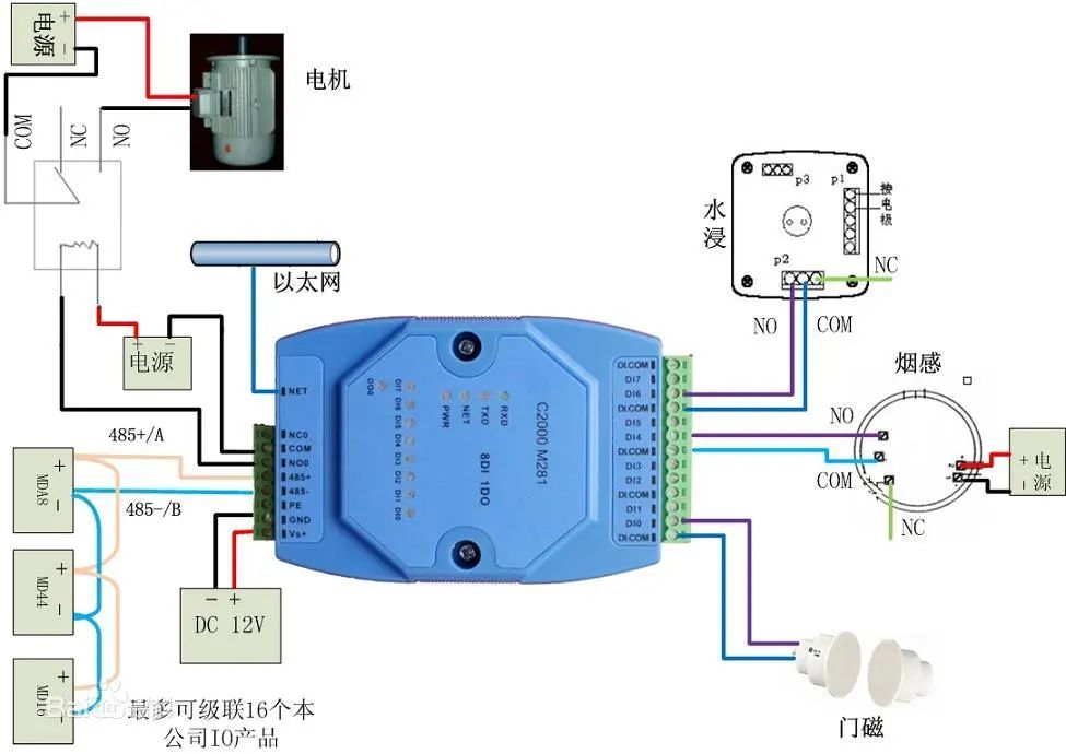
Analog quantities are mostly non-electrical quantities, while PLCs can only handle digital quantities and electrical quantities. Therefore, to achieve conversion between them, sensors are needed to convert analog quantities into digital quantities.
If this electrical quantity is not standard, it must be converted by a transmitter to turn the non-standard electrical quantity into a standard electrical signal, such as 4—20mA, 1—5V, 0—10V, etc.
Additionally, there must be an analog input unit (A/D) to convert these standard electrical signals into digital signals. The analog output unit (D/A) converts the processed digital quantities back into analog quantities—standard electrical signals.
Thus, the conversion between standard electrical signals and digital quantities requires various calculations. This necessitates understanding the resolution of the analog quantity unit and the standard electrical signal.
For example:
If the resolution of the PLC analog unit is 1/32767, corresponding to a standard electrical quantity of 0—10V, and the temperature value to be detected is 0—100℃. Then 0—32767 corresponds to the temperature value of 0—100℃. The digital quantity corresponding to 1℃ is calculated as 327.67. If you want to achieve a temperature value accurate to 0.1℃, divide 327.67 by 10.
Analog quantity control includes: feedback control, feedforward control, proportional control, fuzzy control, etc. These are all calculations involving digital quantities within the PLC.
3. Pulse Quantity is a digital quantity that continuously alternates between 0 (low level) and 1 (high level) (the instantaneous voltage or current jumps from one value to another), and the frequency is defined as the number of pulses changing per second.
The main purpose of PLC pulse quantity control is position control, motion control, trajectory control, etc. For example: the application of pulse count in angle control. The subdivision of the stepper motor driver is 10000 per revolution, requiring the stepper motor to rotate 90 degrees.
Thus, the pulse count to be acted upon = 10000/(360/90) = 2500

PLC Programming Algorithm (2) – Calculation of Analog Quantity
1. -10—10V. When the voltage is -10V—10V, it is converted to F448—0BB8Hex(-3000—3000) at a resolution of 6000; at a resolution of 12000, it is converted to E890—1770Hex(-6000—6000).
2. 0—10V. When the voltage is 0—10V, at a resolution of 12000, it is converted to 0—1770Hex(0—6000); at a resolution of 12000, it is converted to 0—2EE0Hex(0—12000).
3. 0—20mA. When the current is 0—20mA, at a resolution of 6000, it is converted to 0—1770Hex(0—6000); at a resolution of 12000, it is converted to 0—2EE0Hex(0—12000).
4. 4—20mA. When the current is 4—20mA, at a resolution of 6000, it is converted to 0—1770Hex(0—6000); at a resolution of 12000, it is converted to 0—2EE0Hex(0—12000).
This is just a brief introduction; different PLCs have different resolutions, and the range of physical quantities you measure may vary. The calculation results may have some differences.
Note: Requirements for wiring of analog inputs
1. Use shielded twisted pairs, but do not connect the shield layer.
2. When an input is not in use, short-circuit the V IN and COM terminals.
3. Isolate the analog signal lines from the power lines (AC power lines, high voltage lines, etc.).
4. When there is interference on the power line, install a filter between the input part and the power unit.
5. After confirming correct wiring, first power on the CPU unit, then power on the load.
6. When cutting power, first cut off the load’s power supply, then cut off the CPU’s power supply.

Pulse quantity control is often used for stepper motors and servo motors for angle control, distance control, position control, etc. The following illustrates various control methods using stepper motors as an example.
1. Angle control of stepper motors. First, clarify the subdivision of the stepper motor, then determine the total pulse count required for the stepper motor to make one full turn.

Calculate “Angle Percentage = Set Angle / 360° (i.e., one full turn)”
“Angle Action Pulse Count = Total Pulse Count per Turn * Angle Percentage”
The formula is:
Angle Action Pulse Count = Total Pulse Count per Turn * (Set Angle / 360°)
2. Distance control of stepper motors. First, clarify the total pulse count required for one full turn of the stepper motor. Then determine the diameter of the stepper motor’s wheel, calculate the wheel circumference, and calculate the distance traveled per pulse. Finally, calculate the pulse count required for the set distance.

The formula is:
Set Distance Pulse Count = Set Distance / [(Wheel Diameter * 3.14) / Total Pulse Count per Turn]
3. Position control of stepper motors integrates angle control and distance control.
The above is just a simple analysis of the control methods for stepper motors, which may differ from reality and is for reference only.
The action of servo motors is similar to that of stepper motors, but the internal electronic gear ratio and the deceleration ratio of the servo motor must be considered.


ZHINANCHE
Click “Read Original” to sign up for robot courses