Definition of PLC


A programmable logic controller (PLC) is a digital operation electronic system designed for use in industrial environments. It uses programmable memory to store instructions for performing logic operations, sequential control, timing, counting, and arithmetic operations, and controls various types of machinery or production processes through digital and analog inputs and outputs. PLCs and their associated peripheral devices should be designed to easily integrate into an industrial control system and to be easily expandable.

Classification of PLCs


There are many types of PLCs, each with different specifications and performance. PLCs are generally classified based on their structural form, functional differences, and the number of I/O points.
1. Classification by Structural Form
PLCs can be divided into two categories based on their structural form: integral and modular.
(1) Integral PLC
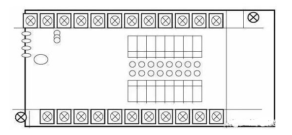
An integral PLC consolidates components such as the power supply, CPU, and I/O interfaces into a single chassis, as shown in the figure. It features a compact structure, small size, and low cost. Small PLCs typically adopt this integral structure. An integral PLC consists of a basic unit (also known as the host) with varying I/O points and expansion units. The basic unit contains the CPU, I/O interfaces, expansion ports connected to I/O expansion units, and interfaces connected to programmers or EPROM writers; the expansion units only contain I/O and power supply, without a CPU. Basic and expansion units are usually connected by flat cables. Integral PLCs can also be equipped with special function units such as analog units and position control units to extend their functionality.
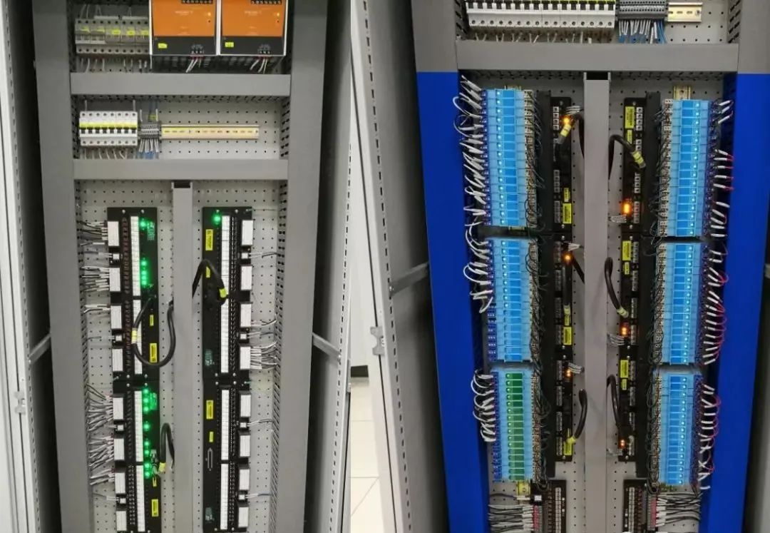
(2) Modular PLC
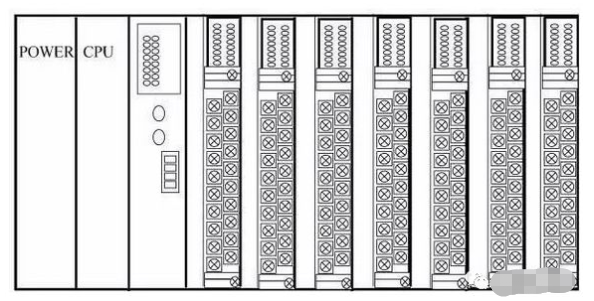
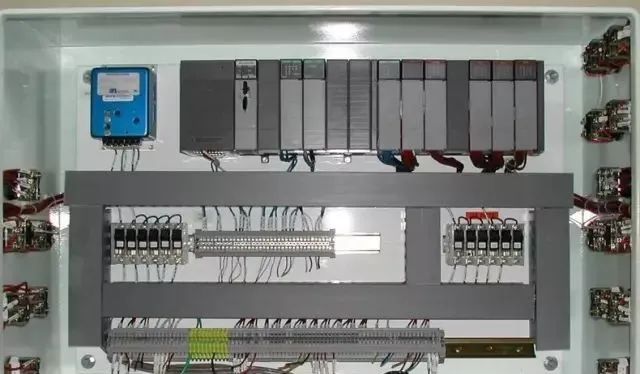
A modular PLC consists of several separate modules for each component, such as CPU modules, I/O modules, power supply modules (some contained within the CPU module), and various functional modules. Modular PLCs consist of a frame or baseboard and various modules, with modules installed in sockets on the frame or baseboard, as shown in the figure. The modular PLC is characterized by flexible configuration, allowing different system scales to be selected as needed, and is easy to assemble, expand, and maintain. Medium and large PLCs generally adopt a modular structure.
Some PLCs combine the characteristics of integral and modular designs, forming what is known as a stacked PLC. The CPU, power supply, and I/O interfaces of a stacked PLC are also independent modules, but they are connected by cables, and each module can be stacked layer by layer. This not only allows for flexible system configuration but also enables compact size.
2. Classification by Function
PLCs can be classified into three categories based on their functions: low-end, mid-range, and high-end.
(1) Low-End PLC
Low-end PLCs have basic functions such as logic operations, timing, counting, shifting, self-diagnosis, and monitoring, and may have a small number of analog inputs/outputs, arithmetic operations, data transfer, comparison, and communication functions. They are primarily used for logic control, sequential control, or limited analog control in standalone control systems.
(2) Mid-Range PLC
In addition to the functions of low-end PLCs, mid-range PLCs have stronger analog input/output capabilities, arithmetic operations, data transfer and comparison, number conversion, remote I/O, subroutine, and network communication functions; some can also add interrupt control and PID control functions, suitable for complex control systems.
(3) High-End PLC
High-end PLCs have all the functions of mid-range PLCs, plus additional capabilities for signed arithmetic operations, matrix operations, bit logic operations, square root operations, and other special function calculations, as well as tabulation and table transfer functions. High-end PLCs have stronger communication and networking capabilities, can be used for large-scale process control, or form distributed network control systems, thus achieving factory automation.
3. Classification by I/O Points
Based on the number of I/O points, PLCs can be classified into small, medium, and large categories.
(1) Small PLC
Small PLCs have fewer than 256 I/O points, typically with a single CPU and an 8-bit or 16-bit processor, and user memory capacity below 4KB. For example: Mitsubishi FX0S series.
(2) Medium PLC
Medium PLCs have I/O points ranging from 256 to 2048, with dual CPUs and user memory capacity of 2 to 8KB.
(3) Large PLC
Large PLCs have more than 2048 I/O points, with multiple CPUs and 16-bit or 32-bit processors, and user memory capacity of 8 to 16KB.
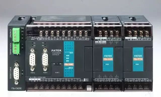
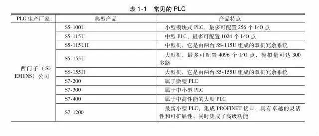
Globally, PLC products can be divided into three main schools based on region: American products, European products, and Japanese products. The PLC technologies of the US and Europe were developed independently in isolation, resulting in significant differences between American and European PLC products. Japanese PLC technology was introduced from the US, inheriting certain aspects of American PLC products, but Japan primarily focuses on small PLCs. The US and Europe are known for medium and large PLCs, while Japan is renowned for small PLCs.
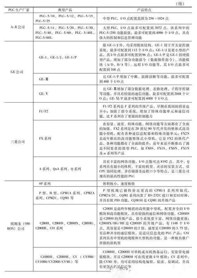
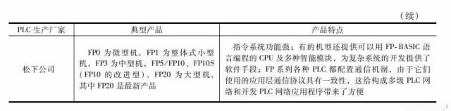
Common PLCs are shown in the table below:

Functions and Application Fields of PLC


PLC combines the advantages of relay contact control and the flexibility and convenience of computers, which gives PLCs many characteristics that other controllers cannot compare.
1. Functions of PLC
PLC is a general industrial automatic control device developed based on microprocessor technology, integrating computer technology, automatic control technology, and communication technology. It has a series of advantages such as high reliability, small size, strong functionality, simple program design, flexibility, and easy maintenance, making it widely used in metallurgy, energy, chemical, transportation, and electric power sectors, becoming one of the three pillars of modern industrial control (PLC, robots, and CAD/CAM). Based on the characteristics of PLCs, their functional forms can be summarized as follows.
(1) Switch Logic Control
PLCs have powerful logic operation capabilities and can achieve various simple and complex logic control. This is the most basic and widely used application field of PLCs, replacing traditional relay contact control.
(2) Analog Control
PLCs are equipped with A/D and D/A conversion modules. The A/D module can convert field analog quantities such as temperature, pressure, flow, and speed into digital quantities, which are then processed by the microprocessor within the PLC (the microprocessor can only process digital quantities), and then control; or converted back into analog quantities through the D/A module to control the controlled object, thus enabling PLC to control analog quantities.
(3) Process Control
Modern medium and large PLCs are generally equipped with PID control modules to perform closed-loop process control. When a variable in the control process deviates, the PLC can calculate the correct output according to the PID algorithm, thereby controlling and adjusting the production process to keep the variable at the set value. Currently, many small PLCs also have PID control functions.
(4) Timing and Counting Control
PLCs have strong timing and counting functions, providing users with dozens or even hundreds or thousands of timers and counters. The timing and counting values can be set by users when writing user programs, or by operators on site through programming devices, thereby achieving timing and counting control. If users need to count high-frequency signals, they can choose high-speed counting modules.
(5) Sequential Control
In industrial control, PLC step instructions or shift register programming can be used to achieve sequential control.
(6) Data Processing
Modern PLCs can perform arithmetic operations, data transfer, sorting, and table lookups, as well as data comparison, conversion, communication, display, and printing, possessing strong data processing capabilities.
(7) Communication and Networking
Most modern PLCs utilize communication and network technologies, with RS-232 or RS-485 interfaces for remote I/O control. Multiple PLCs can network and communicate with each other, and external devices can exchange programs and data signals with one or more programmable controllers, such as program transfers, data document transfers, monitoring, and diagnosis. Communication interfaces or processors complete the transfer of programs and data based on standard hardware interfaces or proprietary communication protocols.
2. Application Fields of PLC
Currently, PLCs are widely used in various industries including steel, petroleum, chemical, electric power, building materials, machinery manufacturing, automotive, textiles, transportation, environmental protection, and cultural entertainment, and their applications can be roughly summarized as follows.
(1) Logic Control of Switch Quantities
This is the most basic and widespread application field of PLCs, replacing traditional relay circuits to achieve logic and sequential control; it can be used for controlling single devices, as well as for multi-machine group control and automated assembly lines, such as injection molding machines, printing machines, staplers, combined machine tools, grinding machines, packaging production lines, and electroplating production lines.
(2) Analog Control
In industrial production processes, many continuously changing quantities, such as temperature, pressure, flow, liquid level, and speed, are analog quantities. To enable PLCs to process analog quantities, A/D and D/A conversions must be achieved. PLC manufacturers produce matching A/D and D/A conversion modules for analog quantity control.
(3) Motion Control
PLCs can be used for controlling circular or linear motion. In terms of control configuration, early systems directly used switch quantity I/O modules to connect position sensors and actuators; now, dedicated motion control modules are generally used, which can drive single-axis or multi-axis position control modules for stepper motors or servo motors. Almost all major PLC manufacturers worldwide offer products with motion control capabilities, widely used in various machinery, machine tools, robots, elevators, etc.
(4) Process Control
Process control refers to the closed-loop control of analog quantities such as temperature, pressure, and flow, which has very wide applications in metallurgy, chemical, heat treatment, and boiler control. As an industrial control computer, PLCs can compile various control algorithm programs to complete closed-loop control. PID regulation is a commonly used method in general closed-loop control systems, and medium and large PLCs are equipped with PID modules; currently, many small PLCs also have this function module. PID processing generally runs specific PID subroutines.
(5) Data Processing
Modern PLCs have mathematical operation capabilities (including matrix operations, function calculations, logical operations), data transfer, data conversion, sorting, table lookups, and bit operations, enabling them to collect, analyze, and process data. This data can be compared with reference values stored in memory to complete certain control operations; it can also be transmitted to other intelligent devices using communication functions or printed out. Data processing is generally used in large control systems, such as unmanned flexible manufacturing systems; it can also be used in process control systems, such as large control systems in papermaking, metallurgy, and food industries.
(6) Communication and Networking
PLC communication includes communication between PLCs and communication between PLCs and other intelligent devices. With the development of computer control, factory automation networks are developing rapidly, and PLC manufacturers are placing great importance on PLC communication functions, each launching their own network systems. Newly produced PLCs generally have communication interfaces, making communication very convenient.

Basic Structure and Working Principle of PLC


As an industrial control computer, a PLC has a structure similar to that of a regular computer; however, due to different usage scenarios and purposes, there are some structural differences.
1. Hardware Components of PLC
The basic structure of the PLC hardware system is as follows:
The PLC host consists of the CPU, memory (EPROM, RAM), input/output units, peripheral I/O interfaces, communication interfaces, and power supply. For integral PLCs, all these components are housed within the same chassis. For modular PLCs, each component is independently packaged as a module, and modules are connected together via racks and cables. The various parts within the host are connected through power buses, control buses, address buses, and data buses, with certain external devices configured according to the actual control objects to form different PLC control systems. Common external devices include programmers, printers, EPROM writers, etc. PLCs can be configured with communication modules to communicate with host computers and other PLCs, forming distributed control systems.
Below, each component of the PLC and its function are introduced to help users further understand the control principles and working processes of PLCs.
(1) CPU
The CPU is the control center of the PLC, coordinating the work of various devices in an orderly manner under its control, thereby achieving control over the field devices. The CPU consists of a microprocessor and a controller, capable of performing logic and mathematical operations, coordinating the work of various parts within the control system.
The controller’s role is to ensure that all parts of the microprocessor work in an orderly manner, with its basic function being to read instructions from memory and execute them.
(2) Memory
The PLC is equipped with two types of memory: system memory and user memory. System memory stores the system management program, which cannot be accessed or modified by users. User memory is used to store the compiled application programs and the working data state. The portion of user memory that stores the working data state is also known as the data storage area, which includes input/output data image areas, timer/counter preset values and current values, and buffers for storing intermediate results.
The PLC’s memory primarily includes the following types:
a. Read-Only Memory
b. Programmable Read-Only Memory
c. Erasable Programmable Read-Only Memory
d. Electrically Erasable Programmable Read-Only Memory
e. Random Access Memory
(3) Input/Output (I/O) Modules
a. Digital Input Modules
Digital input devices include various switches, buttons, sensors, etc. The input types for PLCs can typically be DC, AC, or mixed. The power supply for the input circuit can be provided externally, and some can also be supplied internally by the PLC.
b. Digital Output Modules
The output module’s role is to convert the control signals output by the CPU from TTL levels into signals required by the production site that can drive specific devices, thereby activating the actuators.
(4) Programmer
The programmer is an important external device for PLCs, used to input user programs into the PLC’s user program memory, debug programs, and monitor program execution. Programmers can be categorized into the following three types:
a. Simple Programmer
b. Graphic Programmer
c. General Computer Programmer
(5) Power Supply
The power supply unit converts external power sources (220V AC power) into internal working voltage. The externally connected power is converted into the working power required by the PLC’s internal circuits (DC 5V, ±12V, 24V) through a dedicated switch-type voltage regulator within the PLC, and provides a 24V DC power supply for external input components (for input endpoints only). The power supply for driving the PLC load is provided by the user.
(6) Peripheral Interfaces
The peripheral interface circuit is used to connect handheld programmers or other graphic programmers, text displays, and can form a control network for the PLC through peripheral interfaces. The PLC connects to computers via RS-485 interfaces using PC/PPI cables or MPI cards, enabling programming, monitoring, networking, etc.
2. Software Components of PLC
The PLC software consists of system programs and user programs.
The system program is designed and written by the PLC manufacturer and stored in the PLC’s system memory, which users cannot directly read or modify. The system program generally includes system diagnostic programs, input processing programs, compilation programs, information transfer programs, and monitoring programs.
The user program of the PLC is compiled by users according to control requirements using the PLC’s programming language. In PLC applications, the most important aspect is to write user programs using the PLC’s programming language to achieve control objectives. Since PLCs are specifically developed for industrial control, their main users are electrical technicians, and to meet their traditional habits and capabilities, the primary programming languages of PLCs are simpler, more understandable, and more visual compared to computer languages.
a. Graphic Instruction Structure
b. Clear Variable Constants
c. Simplified Program Structure
d. Simplified Application Software Generation Process
e. Enhanced Debugging Methods

Basic Working Principle of PLC


The PLC scanning work mode is mainly divided into three stages: input sampling stage, user program execution stage, and output refresh stage, as shown in the figure.
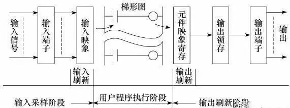
1. Input Sampling Stage
In the input sampling stage, the PLC reads all input states and data sequentially in a scanning manner and stores them in the corresponding units within the I/O image area. After the input sampling is complete, it transitions to the user program execution and output refresh stages. During these two stages, even if the input states and data change, the states and data in the corresponding units of the I/O image area do not change. Therefore, if the input is a pulse signal, the width of that pulse signal must exceed one scanning cycle to ensure that it can be read under any circumstances.
2. User Program Execution Stage
In the user program execution stage, the PLC scans the user program (ladder diagram) sequentially from top to bottom. When scanning each ladder diagram, it first scans the control circuits composed of various contacts on the left side of the ladder diagram and performs logic operations on the control circuits in the order of left to right and top to bottom; then, based on the results of the logic operations, it refreshes the state of the corresponding bits in the system RAM storage area or the corresponding bits in the I/O image area, or determines whether to execute the special function instructions specified by the ladder diagram. During the execution of the user program, only the input points in the I/O image area maintain their states and data, while other output points and soft devices in the I/O image area or system RAM storage area may change, and the execution results of the ladder diagrams positioned above will affect those below that use these coils or data; conversely, the ladder diagrams below will only affect those above in the next scanning cycle.
3. Output Refresh Stage
After the user program scanning is complete, the PLC enters the output refresh stage. During this period, the CPU refreshes all output latch circuits according to the states and data in the I/O image area, then drives the corresponding external devices through the output circuits. This is when the PLC’s actual output occurs.

Input/Output Lag Phenomenon


From the working process of PLCs, the following conclusions can be drawn:
1. Programs are executed in a scanning manner, and there is a theoretical lag in the logical relationship between input/output signals. The longer the scanning cycle, the more severe the lag.
2. The scanning cycle includes not only the time occupied by the three main working stages: input sampling, user program execution, and output refresh, but also the time taken by system management operations. The execution time of the program relates to the length of the program and the complexity of the instruction operations, while other factors remain largely unchanged. The scanning cycle is generally in the nanosecond range.
3. When executing the program for the nth time, the input data it relies on is based on the sampling values X from the input sampling phase of the current scanning cycle, while the output data relies on the previous output values Y(n-1) and the current output value Yn; the signal sent to the output terminal is the final result Yn after executing all calculations.
4. Input/output response lag is influenced by both the scanning method and the arrangement of the program design.
Complete question bank for the 2021 Electrical Worker Junior Exam (including answers)
Is troubleshooting frequency converters difficult? Just one click!
Can you sweep all electrical exam questions with one click? This tool is a must-have!
Which of the five major electrical drawing software (CAD, Eplan, CADe_simu…) do you prefer?
Latest electrical version of CAD drawing software, with super detailed installation tutorial!
Latest electrical drawing software EPLAN, with super detailed installation tutorial!
Common issues for beginners using S7-200 SMART programming software (with download link)
Comprehensive electrical calculation EXCEL spreadsheets, automatically generated! No need to seek help for electrical calculations!
Bluetooth headphones and electrical/PLC introductory books are available for you to claim? Come and get your electrical gifts!
Basic skills in PLC programming: Ladder diagrams and control circuits (including 1164 practical cases of Mitsubishi PLC)
Can’t understand electrical diagrams yet? Get the basics of electrical drawing and simulation software to quickly get started!
12 free electrical video courses, 10GB of software/e-books, and 30 days of free live electrical courses are available!